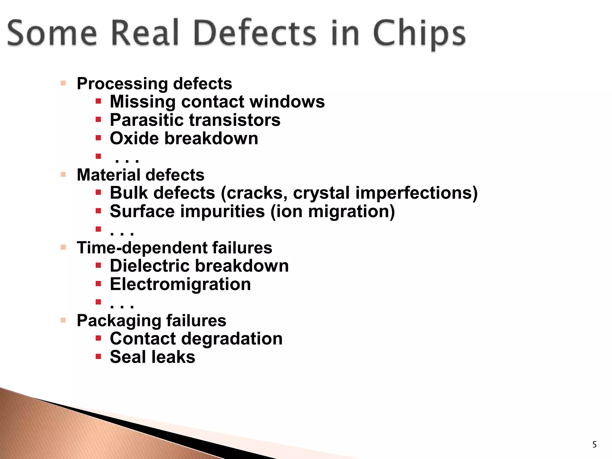
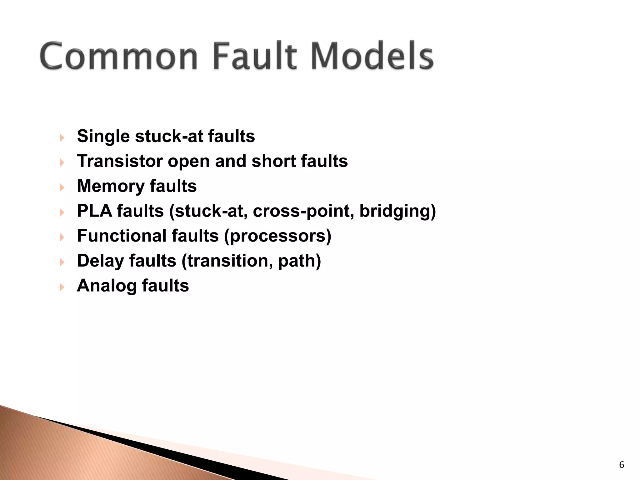
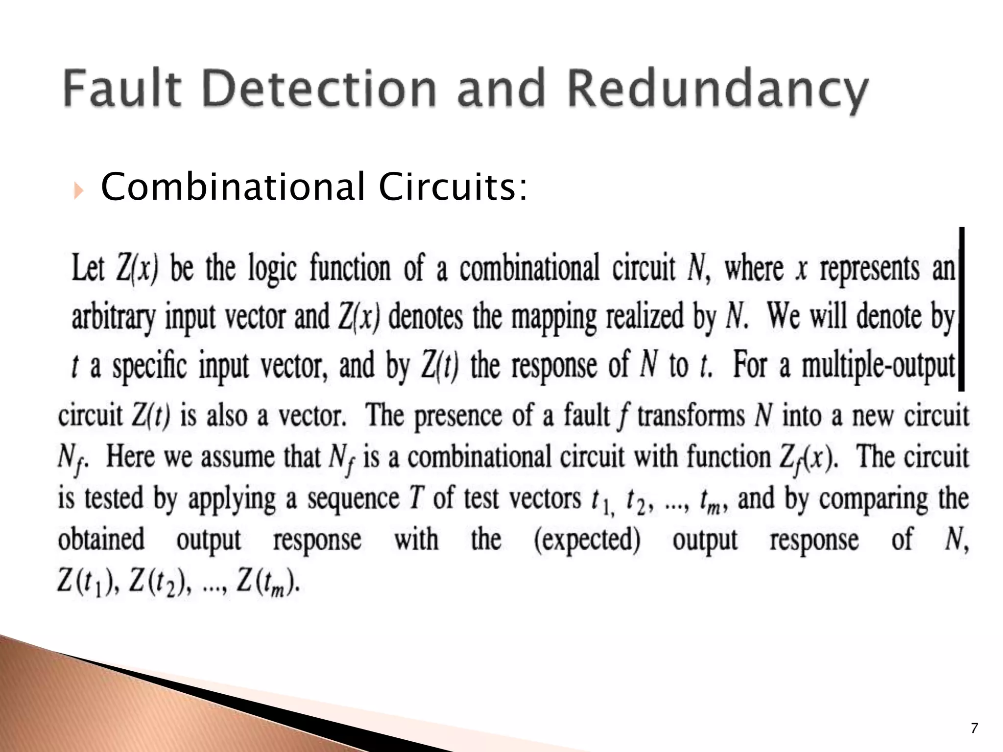
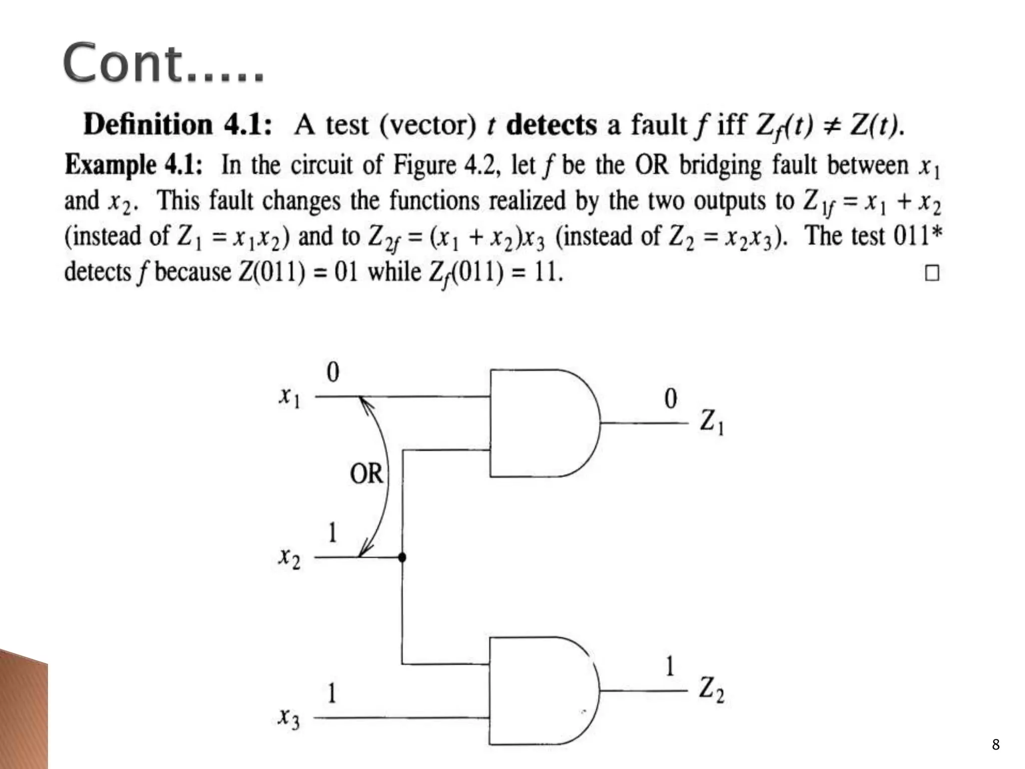
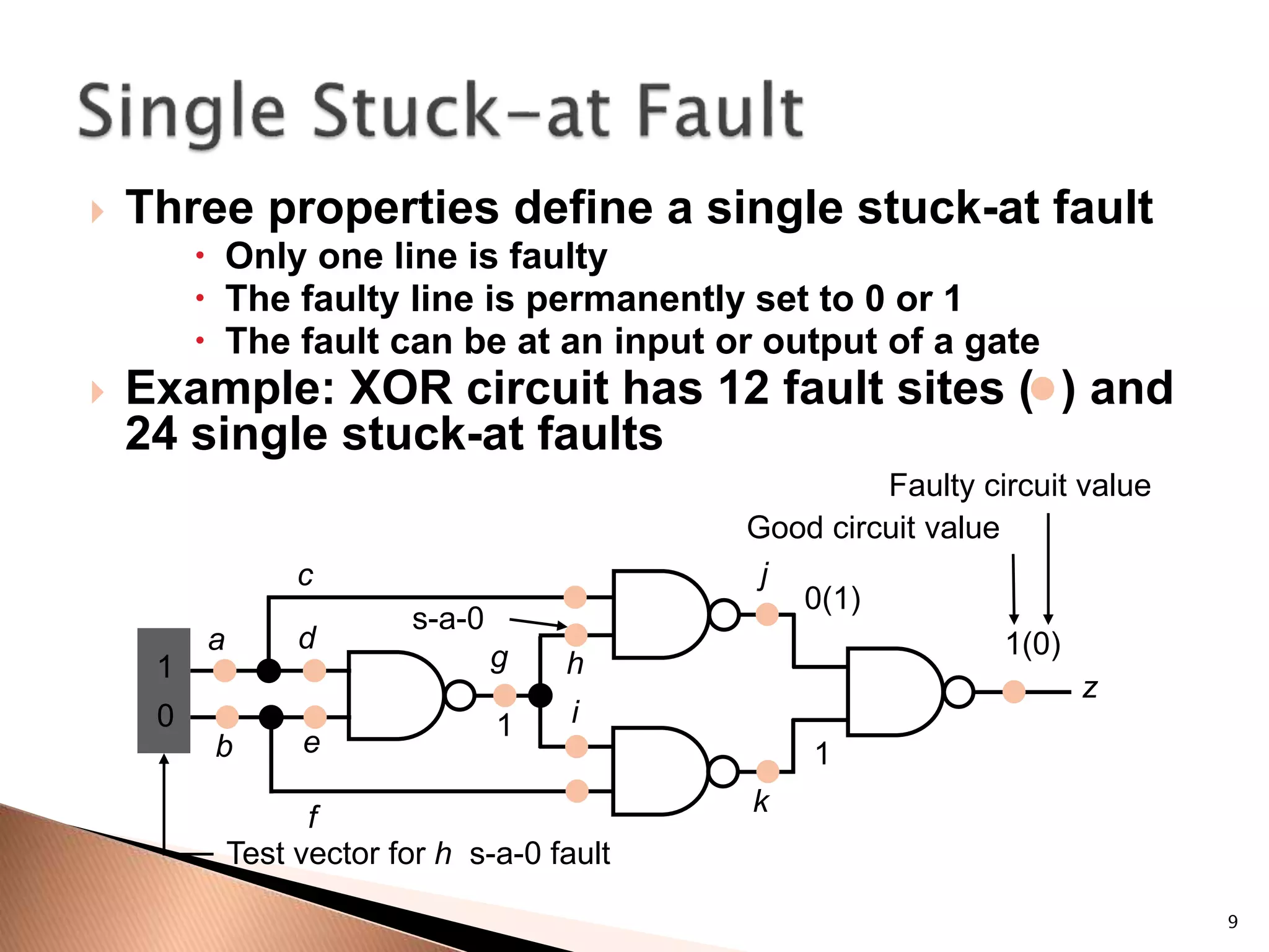
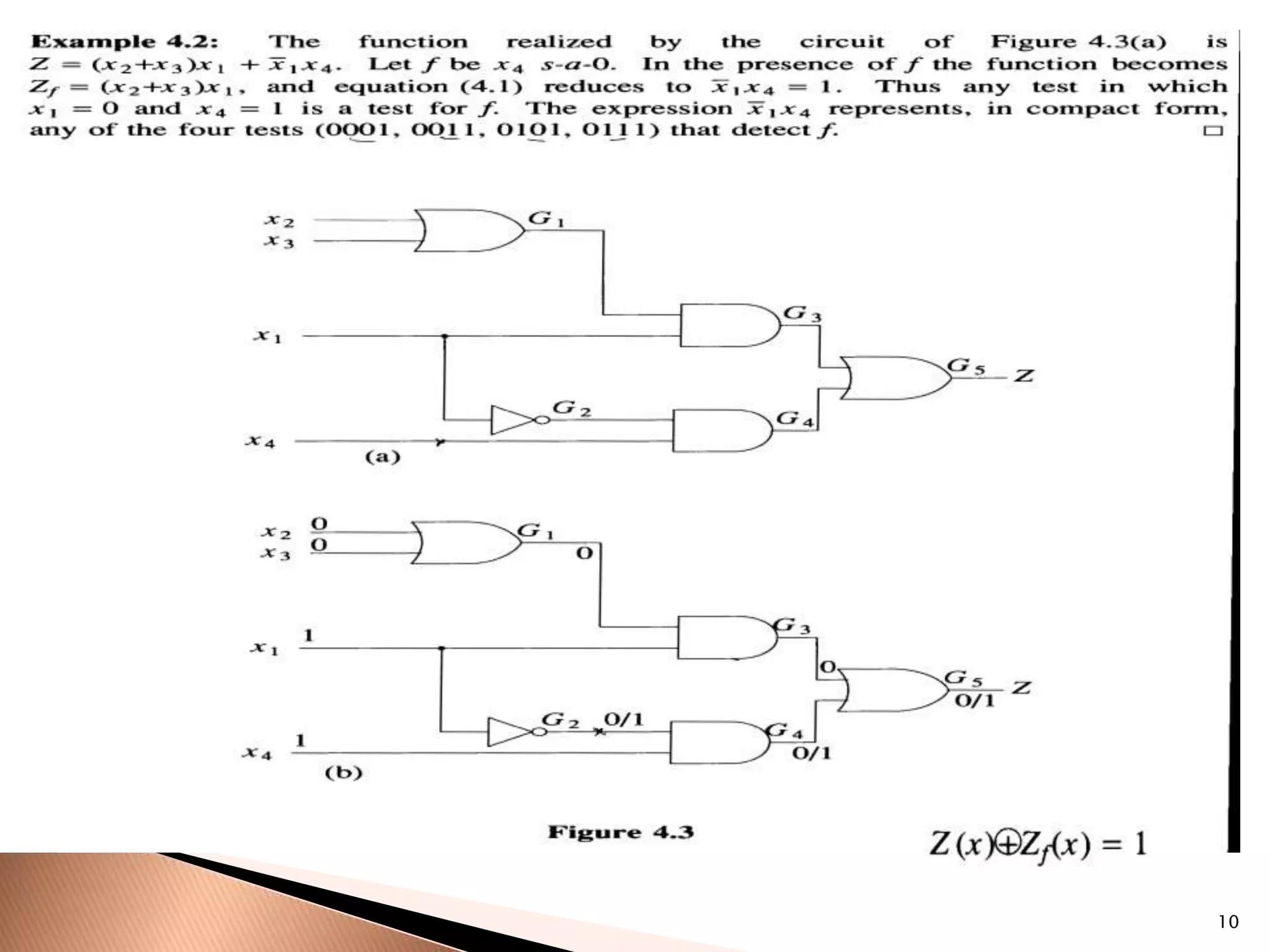
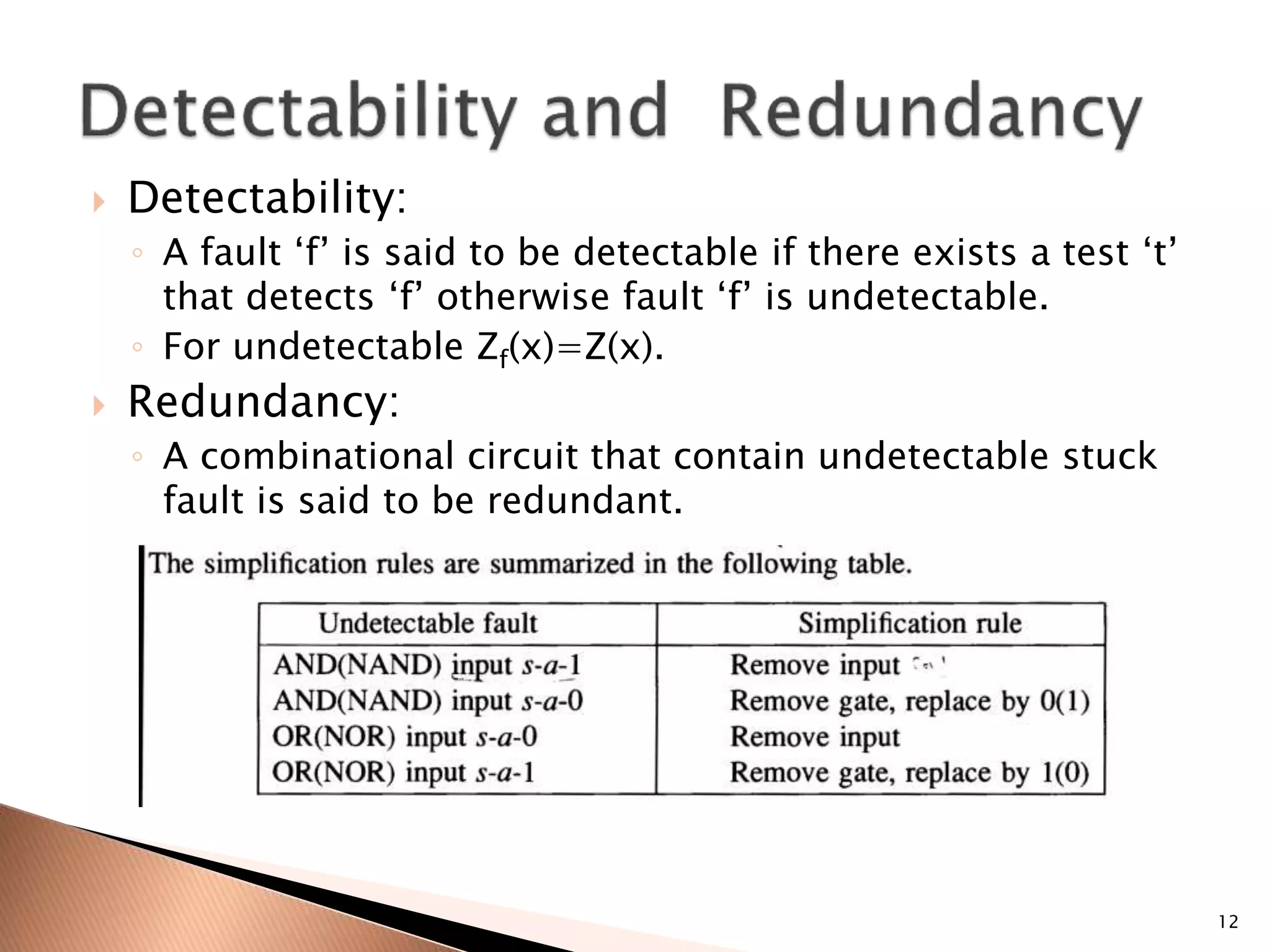
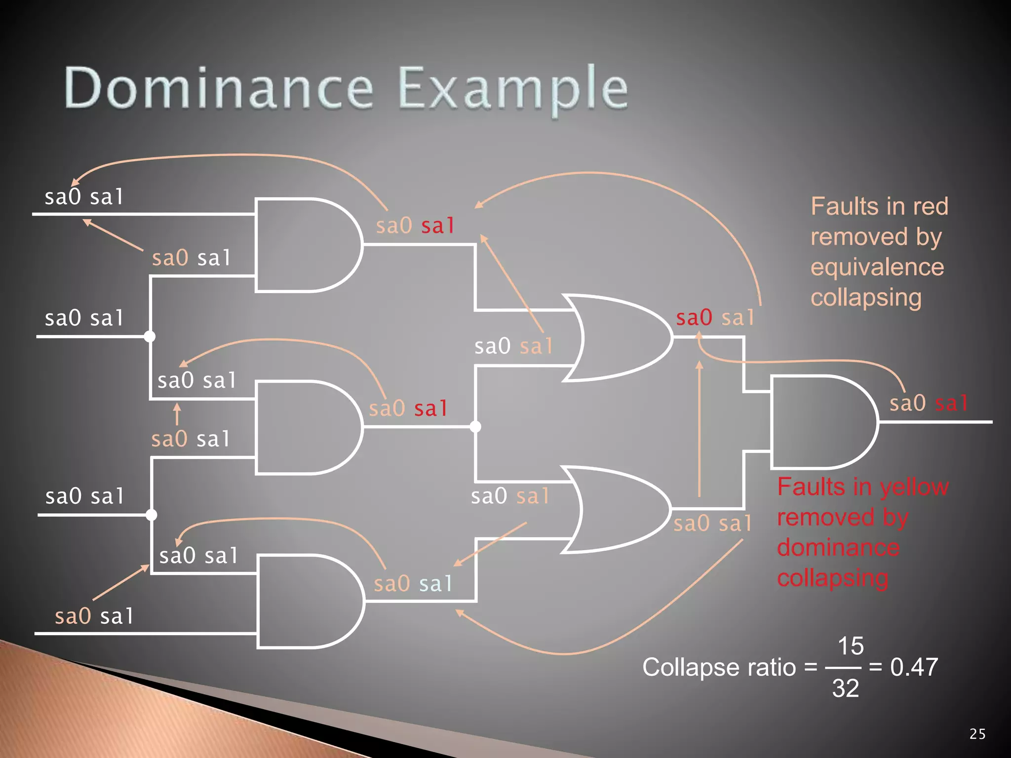
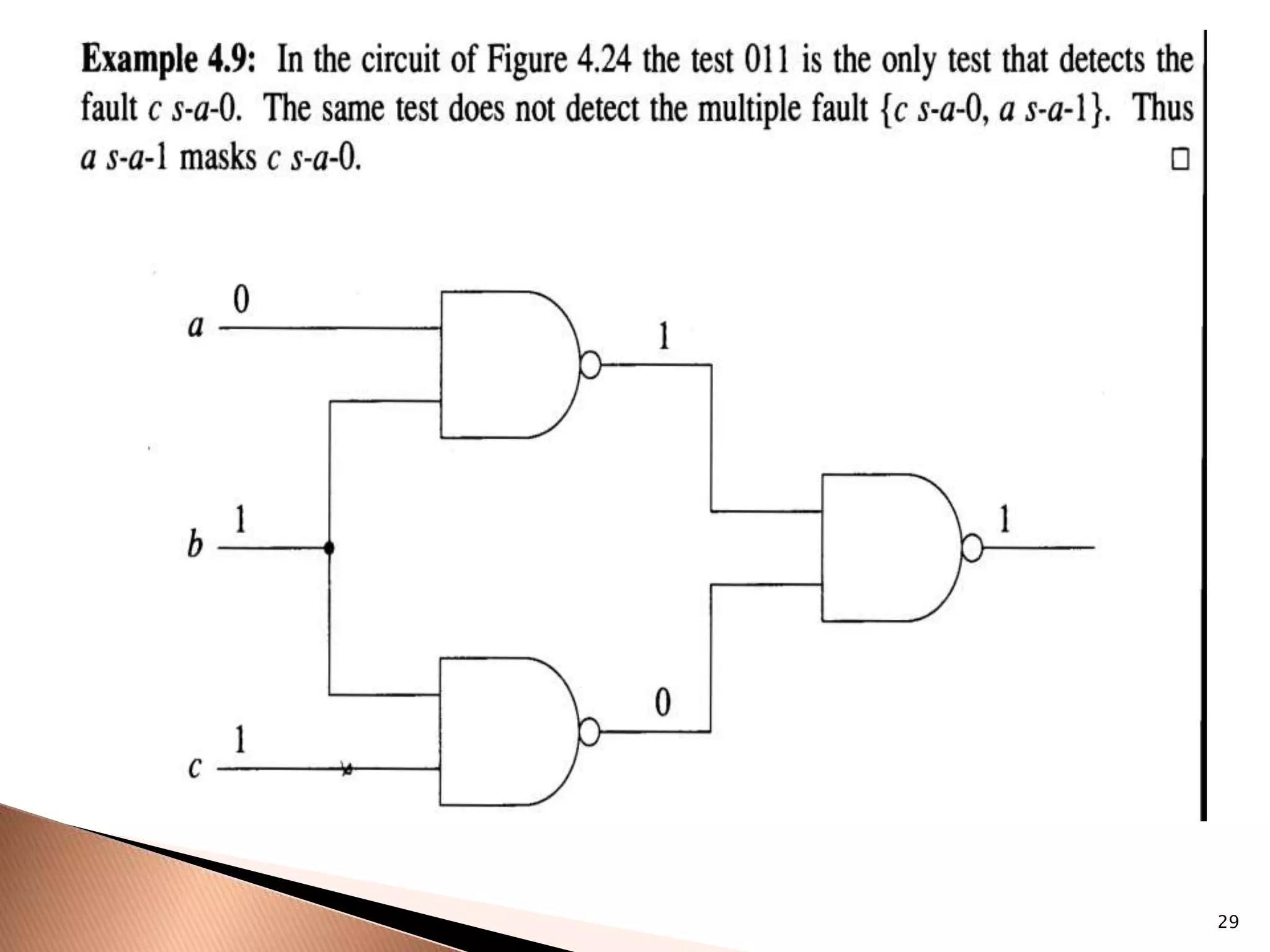
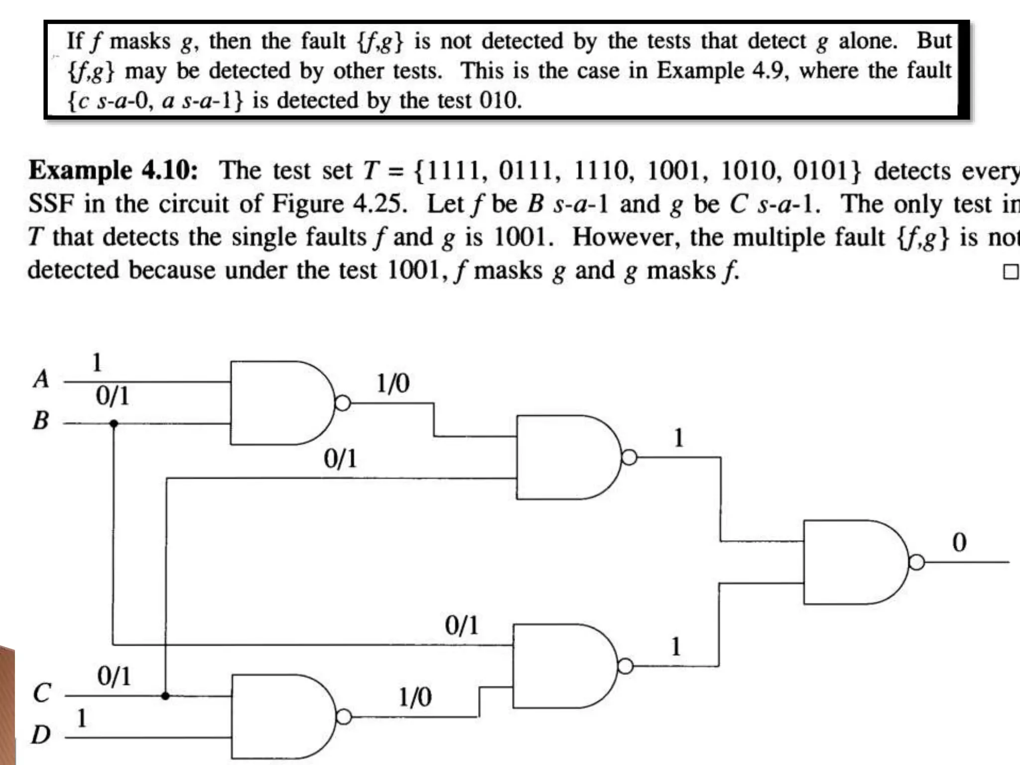
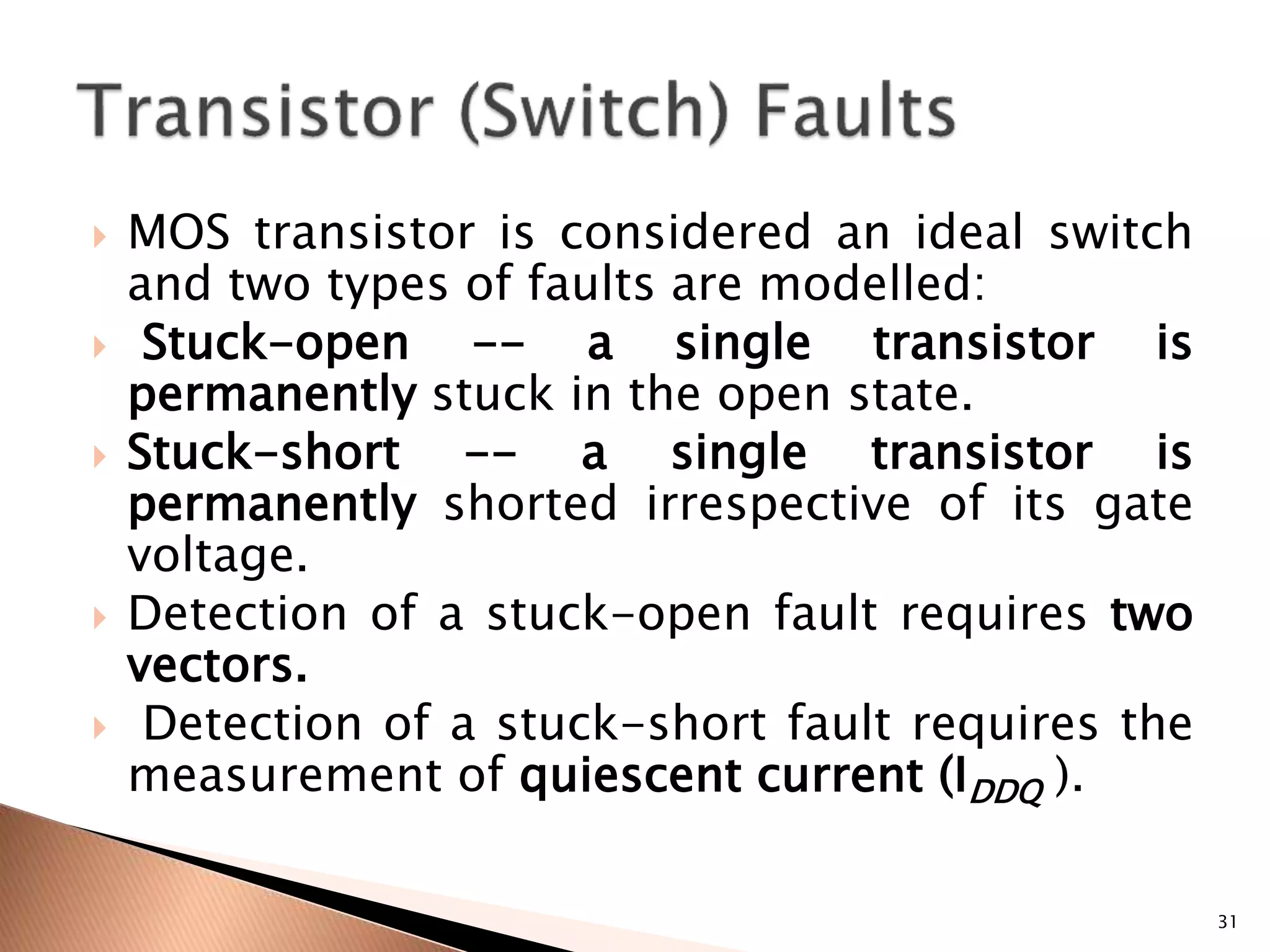
Pg. No93 to 126.
M.Abramovici, M.A. Breuer, A.D. Friedman, “Digital
systems testing and testable design”, Jaico Publishing
House
1
 Fault Modelling and Fault Simulation:
◦ Logical fault models, Fault detection and
Redundancy, Fault equivalence and fault location,
Fault Dominance, Single stuck-fault models,
Multiple stuck fault model, stuck RTL variables,
Fault variables. Testing for single stuck fault and
Bridging fault, General fault simulation techniques,
Serial and Parallel fault simulation, Deductive fault
simulation, Concurrent fault simulation, Fault
simulation for combinational circuits, Fault
sampling, Statistical fault analysis.
2
3
 Why model faults?
 Some real defects in VLSI and PCB
 Common fault models
 Stuck-at faults
 Single stuck-at faults
 Fault equivalence
 Fault dominance and checkpoint theorem
 Classes of stuck-at faults and multiple faults
 Transistor faults
4
 I/O function tests inadequate for
manufacturing (functionality versus
component and interconnect testing)
 Real defects (often mechanical) too
numerous and often not analyzable
 A fault model identifies targets for testing
 A fault model makes analysis possible
 Effectiveness measurable by experiments
5
 Processing defects
 Missing contact windows
 Parasitic transistors
 Oxide breakdown
 . . .
 Material defects
 Bulk defects (cracks, crystal imperfections)
 Surface impurities (ion migration)
 . . .
 Time-dependent failures
 Dielectric breakdown
 Electromigration
 . . .
 Packaging failures
 Contact degradation
 Seal leaks
6
 Single stuck-at faults
 Transistor open and short faults
 Memory faults
 PLA faults (stuck-at, cross-point, bridging)
 Functional faults (processors)
 Delay faults (transition, path)
 Analog faults
 Combinational Circuits:
7
8
9
 Three properties define a single stuck-at fault
 Only one line is faulty
 The faulty line is permanently set to 0 or 1
 The fault can be at an input or output of a gate
 Example: XOR circuit has 12 fault sites ( ) and
24 single stuck-at faults
a
b
c
d
e
f
1
0
g h
i
1
s-a-0
j
k
z
0(1)
1(0)
1
Test vector for h s-a-0 fault
Good circuit value
Faulty circuit value
10
 Test ‘t’ that detects fault ‘f’ generates error in
values.
 Test ‘t’ propagates the error to primary
outputs
 A line whose value in test ‘t’ changes in
presence of ‘f’ called sensitized to the fault.
 A path composed of sensitized lines is called
sensitized path
11
 Detectability:
◦ A fault ‘f’ is said to be detectable if there exists a test ‘t’
that detects ‘f’ otherwise fault ‘f’ is undetectable.
◦ For undetectable Zf(x)=Z(x).
 Redundancy:
◦ A combinational circuit that contain undetectable stuck
fault is said to be redundant.
12
13
E SA0
F SA1
a SA1
Undetectable
14
15
SA1
16
17
18
19
 Number of fault sites in a Boolean gate circuit is
= #PI + #gates + # (fanout branches)
 Fault equivalence: Two faults f1 and f2 are
equivalent if all tests that detect f1 also detect f2.
 If faults f1 and f2 are equivalent then the
corresponding faulty functions are identical.
 Fault collapsing: All single faults of a logic circuit
can be divided into disjoint equivalence subsets,
where all faults in a subset are mutually equivalent.
A collapsed fault set contains one fault from each
equivalence subset.
20
sa0 sa1
sa0 sa1
sa0 sa1
sa0 sa1
sa0 sa1
sa0 sa1
sa0 sa1
sa0 sa1
sa0 sa1
sa0 sa1
sa0 sa1
sa0 sa1
sa0
sa1
sa0
sa1
sa0
sa0
sa1
sa1
sa0
sa0
sa0
sa1
sa1
sa1
AND
NAND
OR
NOR
WIRE
NOT
FANOUT
21
sa0 sa1
sa0 sa1
sa0 sa1
sa0 sa1
sa0 sa1
sa0 sa1
sa0 sa1
sa0 sa1
sa0 sa1
sa0 sa1
sa0 sa1
sa0 sa1
sa0 sa1
sa0 sa1
sa0 sa1
sa0 sa1
Faults in boldface
removed by
equivalence
collapsing
20
Collapse ratio = ── = 0.625
32
22
 If all tests of some fault F1 detect another fault F2,
then F2 is said to dominate F1.
 Dominance fault collapsing: If fault F2 dominates
F1, then F1 is removed from the fault list.
 When dominance fault collapsing is used, it is
sufficient to consider only the input faults of
Boolean gates. See the next example.
 In a tree circuit (without fanouts) PI faults form a
dominance collapsed fault set.
 If two faults dominate each other then they are
equivalent.
23
24
s-a-1
F1
s-a-1
F2
001
110 010
000
101
100
011
All tests of F2
Only test of F1
s-a-1
s-a-1
s-a-1
s-a-0
A dominance collapsed fault set
25
sa0 sa1
sa0 sa1
sa0 sa1
sa0 sa1
sa0 sa1
sa0 sa1
sa0 sa1
sa0 sa1
sa0 sa1
sa0 sa1
sa0 sa1
sa0 sa1
sa0 sa1
sa0 sa1
sa0 sa1
sa0 sa1
Faults in red
removed by
equivalence
collapsing
15
Collapse ratio = ── = 0.47
32
Faults in yellow
removed by
dominance
collapsing
26
 Primary inputs and fanout branches of a
combinational circuit are called checkpoints.
 Checkpoint theorem: A test set that detects all
single (multiple) stuck-at faults on all checkpoints
of a combinational circuit, also detects all single
(multiple) stuck-at faults in that circuit.
Total fault sites = 16
Checkpoints ( ) = 10
27
 Following classes of single stuck-at faults are
identified by fault simulators:
 Potentially-detectable fault -- Test produces an unknown
(X) state at primary output (PO); detection is
probabilistic, usually with 50% probability.
 Initialization fault -- Fault prevents initialization of the
faulty circuit; can be detected as a potentially-detectable
fault.
 Hyperactive fault -- Fault induces much internal signal
activity without reaching PO.
 Redundant fault -- No test exists for the fault.
 Untestable fault -- Test generator is unable to find a test.
28
 A multiple stuck-at fault means that any set of
lines is stuck-at some combination of (0,1)
values.
 The total number of single and multiple stuck-at
faults in a circuit with k single fault sites is 3k-1.
 A single fault test can fail to detect the target
fault if another fault is also present, however,
such masking of one fault by another is rare.
 Statistically, single fault tests cover a very large
number of multiple faults.
29
30
 MOS transistor is considered an ideal switch
and two types of faults are modelled:
 Stuck-open -- a single transistor is
permanently stuck in the open state.
 Stuck-short -- a single transistor is
permanently shorted irrespective of its gate
voltage.
 Detection of a stuck-open fault requires two
vectors.
 Detection of a stuck-short fault requires the
measurement of quiescent current (IDDQ ).
31

L1_fault modeling_121.pptx

  • 1.
    Pg. No93 to126. M.Abramovici, M.A. Breuer, A.D. Friedman, “Digital systems testing and testable design”, Jaico Publishing House 1
  • 2.
     Fault Modellingand Fault Simulation: ◦ Logical fault models, Fault detection and Redundancy, Fault equivalence and fault location, Fault Dominance, Single stuck-fault models, Multiple stuck fault model, stuck RTL variables, Fault variables. Testing for single stuck fault and Bridging fault, General fault simulation techniques, Serial and Parallel fault simulation, Deductive fault simulation, Concurrent fault simulation, Fault simulation for combinational circuits, Fault sampling, Statistical fault analysis. 2
  • 3.
    3  Why modelfaults?  Some real defects in VLSI and PCB  Common fault models  Stuck-at faults  Single stuck-at faults  Fault equivalence  Fault dominance and checkpoint theorem  Classes of stuck-at faults and multiple faults  Transistor faults
  • 4.
    4  I/O functiontests inadequate for manufacturing (functionality versus component and interconnect testing)  Real defects (often mechanical) too numerous and often not analyzable  A fault model identifies targets for testing  A fault model makes analysis possible  Effectiveness measurable by experiments
  • 5.
    5  Processing defects Missing contact windows  Parasitic transistors  Oxide breakdown  . . .  Material defects  Bulk defects (cracks, crystal imperfections)  Surface impurities (ion migration)  . . .  Time-dependent failures  Dielectric breakdown  Electromigration  . . .  Packaging failures  Contact degradation  Seal leaks
  • 6.
    6  Single stuck-atfaults  Transistor open and short faults  Memory faults  PLA faults (stuck-at, cross-point, bridging)  Functional faults (processors)  Delay faults (transition, path)  Analog faults
  • 7.
  • 8.
  • 9.
    9  Three propertiesdefine a single stuck-at fault  Only one line is faulty  The faulty line is permanently set to 0 or 1  The fault can be at an input or output of a gate  Example: XOR circuit has 12 fault sites ( ) and 24 single stuck-at faults a b c d e f 1 0 g h i 1 s-a-0 j k z 0(1) 1(0) 1 Test vector for h s-a-0 fault Good circuit value Faulty circuit value
  • 10.
  • 11.
     Test ‘t’that detects fault ‘f’ generates error in values.  Test ‘t’ propagates the error to primary outputs  A line whose value in test ‘t’ changes in presence of ‘f’ called sensitized to the fault.  A path composed of sensitized lines is called sensitized path 11
  • 12.
     Detectability: ◦ Afault ‘f’ is said to be detectable if there exists a test ‘t’ that detects ‘f’ otherwise fault ‘f’ is undetectable. ◦ For undetectable Zf(x)=Z(x).  Redundancy: ◦ A combinational circuit that contain undetectable stuck fault is said to be redundant. 12
  • 13.
    13 E SA0 F SA1 aSA1 Undetectable
  • 14.
  • 15.
  • 16.
  • 17.
  • 18.
  • 19.
    19  Number offault sites in a Boolean gate circuit is = #PI + #gates + # (fanout branches)  Fault equivalence: Two faults f1 and f2 are equivalent if all tests that detect f1 also detect f2.  If faults f1 and f2 are equivalent then the corresponding faulty functions are identical.  Fault collapsing: All single faults of a logic circuit can be divided into disjoint equivalence subsets, where all faults in a subset are mutually equivalent. A collapsed fault set contains one fault from each equivalence subset.
  • 20.
    20 sa0 sa1 sa0 sa1 sa0sa1 sa0 sa1 sa0 sa1 sa0 sa1 sa0 sa1 sa0 sa1 sa0 sa1 sa0 sa1 sa0 sa1 sa0 sa1 sa0 sa1 sa0 sa1 sa0 sa0 sa1 sa1 sa0 sa0 sa0 sa1 sa1 sa1 AND NAND OR NOR WIRE NOT FANOUT
  • 21.
    21 sa0 sa1 sa0 sa1 sa0sa1 sa0 sa1 sa0 sa1 sa0 sa1 sa0 sa1 sa0 sa1 sa0 sa1 sa0 sa1 sa0 sa1 sa0 sa1 sa0 sa1 sa0 sa1 sa0 sa1 sa0 sa1 Faults in boldface removed by equivalence collapsing 20 Collapse ratio = ── = 0.625 32
  • 22.
    22  If alltests of some fault F1 detect another fault F2, then F2 is said to dominate F1.  Dominance fault collapsing: If fault F2 dominates F1, then F1 is removed from the fault list.  When dominance fault collapsing is used, it is sufficient to consider only the input faults of Boolean gates. See the next example.  In a tree circuit (without fanouts) PI faults form a dominance collapsed fault set.  If two faults dominate each other then they are equivalent.
  • 23.
  • 24.
    24 s-a-1 F1 s-a-1 F2 001 110 010 000 101 100 011 All testsof F2 Only test of F1 s-a-1 s-a-1 s-a-1 s-a-0 A dominance collapsed fault set
  • 25.
    25 sa0 sa1 sa0 sa1 sa0sa1 sa0 sa1 sa0 sa1 sa0 sa1 sa0 sa1 sa0 sa1 sa0 sa1 sa0 sa1 sa0 sa1 sa0 sa1 sa0 sa1 sa0 sa1 sa0 sa1 sa0 sa1 Faults in red removed by equivalence collapsing 15 Collapse ratio = ── = 0.47 32 Faults in yellow removed by dominance collapsing
  • 26.
    26  Primary inputsand fanout branches of a combinational circuit are called checkpoints.  Checkpoint theorem: A test set that detects all single (multiple) stuck-at faults on all checkpoints of a combinational circuit, also detects all single (multiple) stuck-at faults in that circuit. Total fault sites = 16 Checkpoints ( ) = 10
  • 27.
    27  Following classesof single stuck-at faults are identified by fault simulators:  Potentially-detectable fault -- Test produces an unknown (X) state at primary output (PO); detection is probabilistic, usually with 50% probability.  Initialization fault -- Fault prevents initialization of the faulty circuit; can be detected as a potentially-detectable fault.  Hyperactive fault -- Fault induces much internal signal activity without reaching PO.  Redundant fault -- No test exists for the fault.  Untestable fault -- Test generator is unable to find a test.
  • 28.
    28  A multiplestuck-at fault means that any set of lines is stuck-at some combination of (0,1) values.  The total number of single and multiple stuck-at faults in a circuit with k single fault sites is 3k-1.  A single fault test can fail to detect the target fault if another fault is also present, however, such masking of one fault by another is rare.  Statistically, single fault tests cover a very large number of multiple faults.
  • 29.
  • 30.
  • 31.
     MOS transistoris considered an ideal switch and two types of faults are modelled:  Stuck-open -- a single transistor is permanently stuck in the open state.  Stuck-short -- a single transistor is permanently shorted irrespective of its gate voltage.  Detection of a stuck-open fault requires two vectors.  Detection of a stuck-short fault requires the measurement of quiescent current (IDDQ ). 31