Downloaded 5,526 times


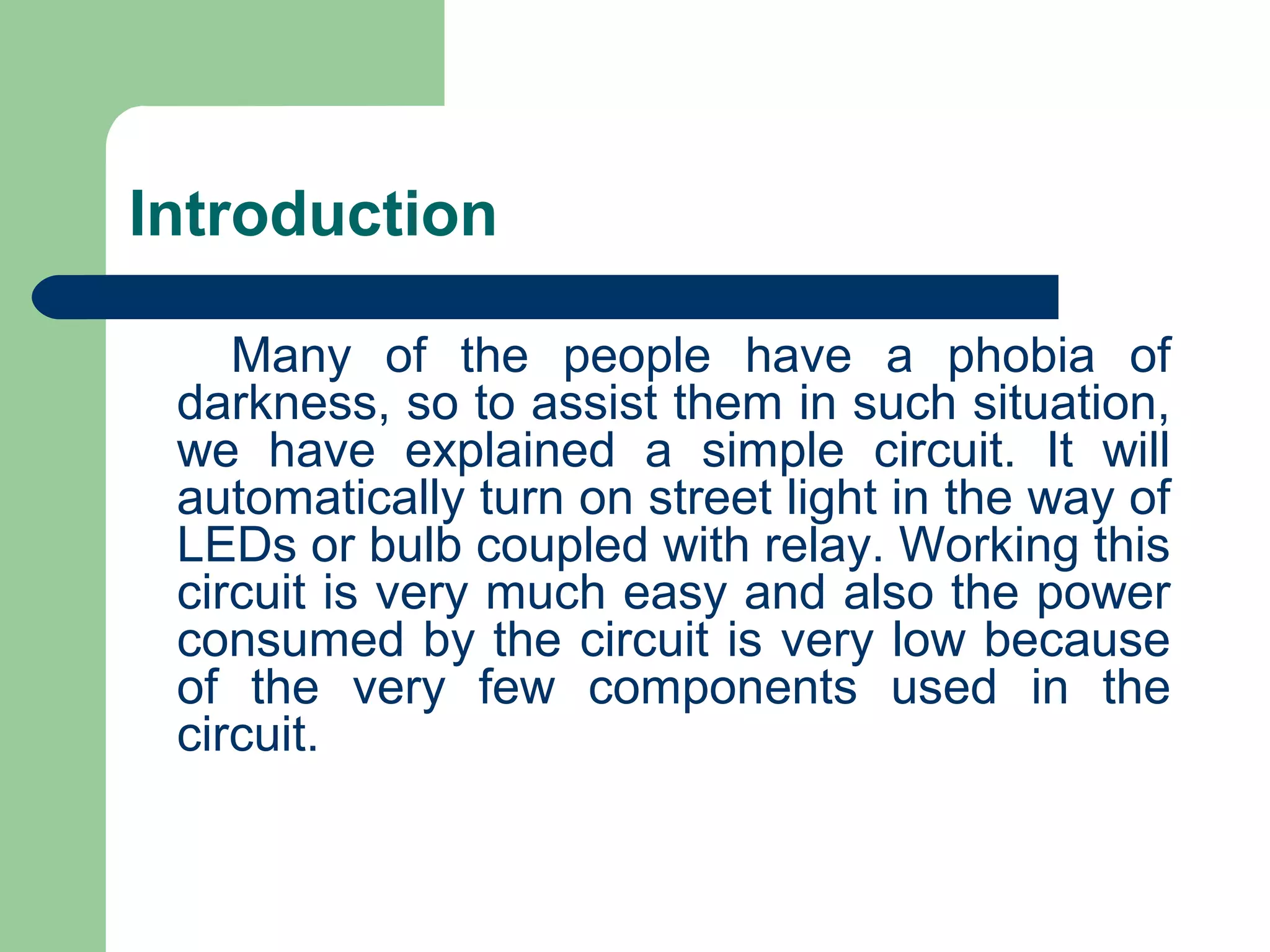
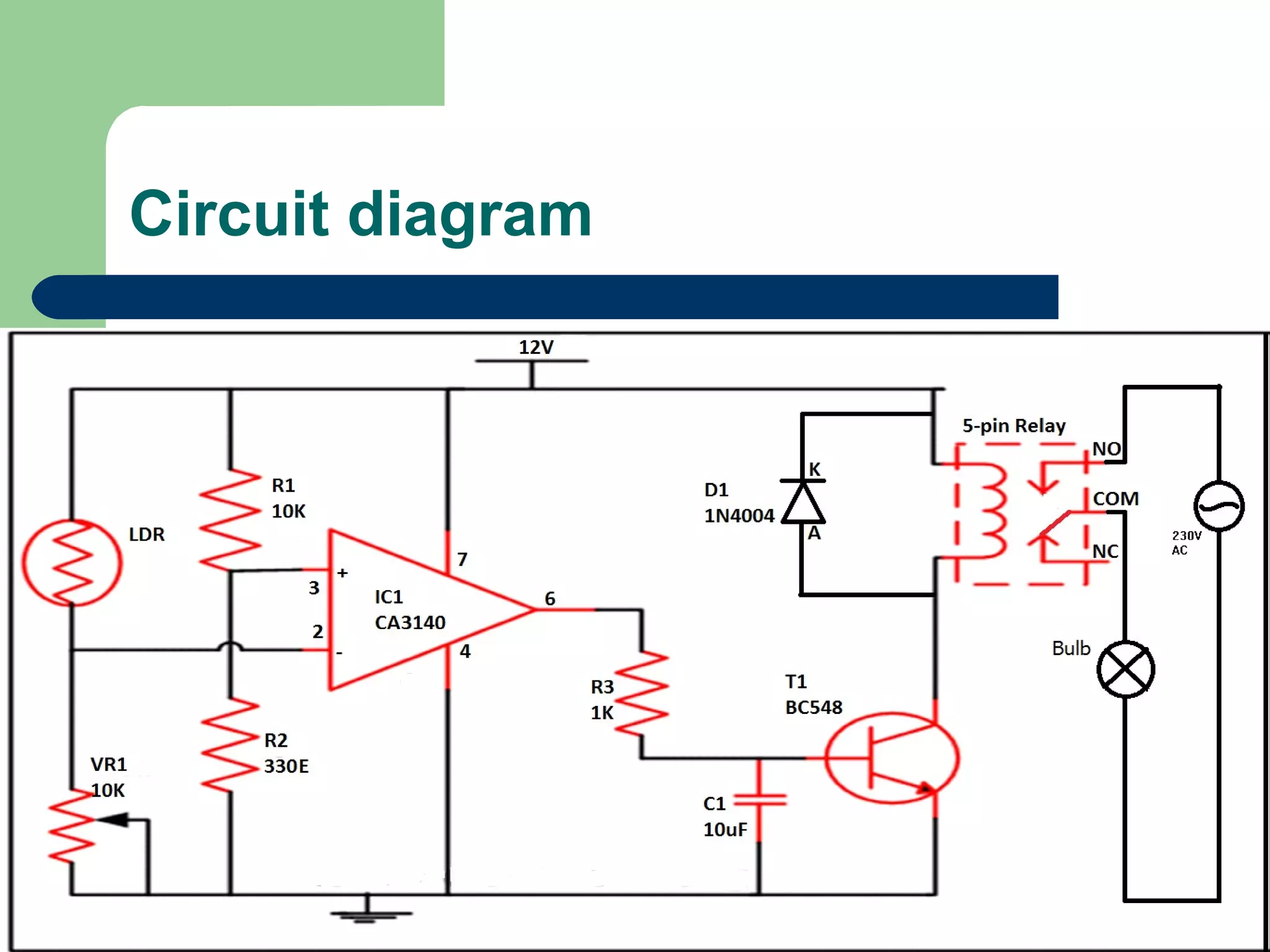
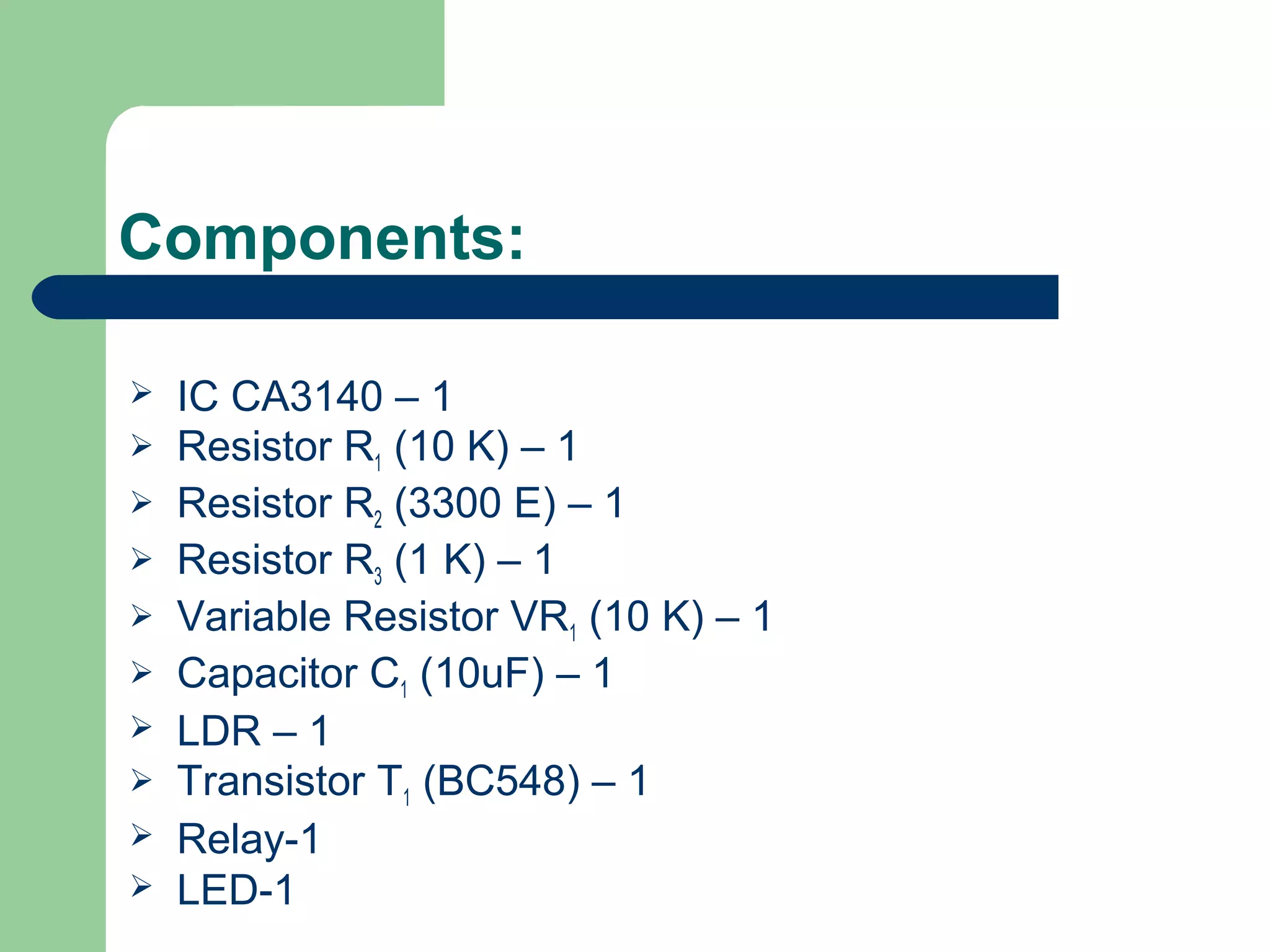
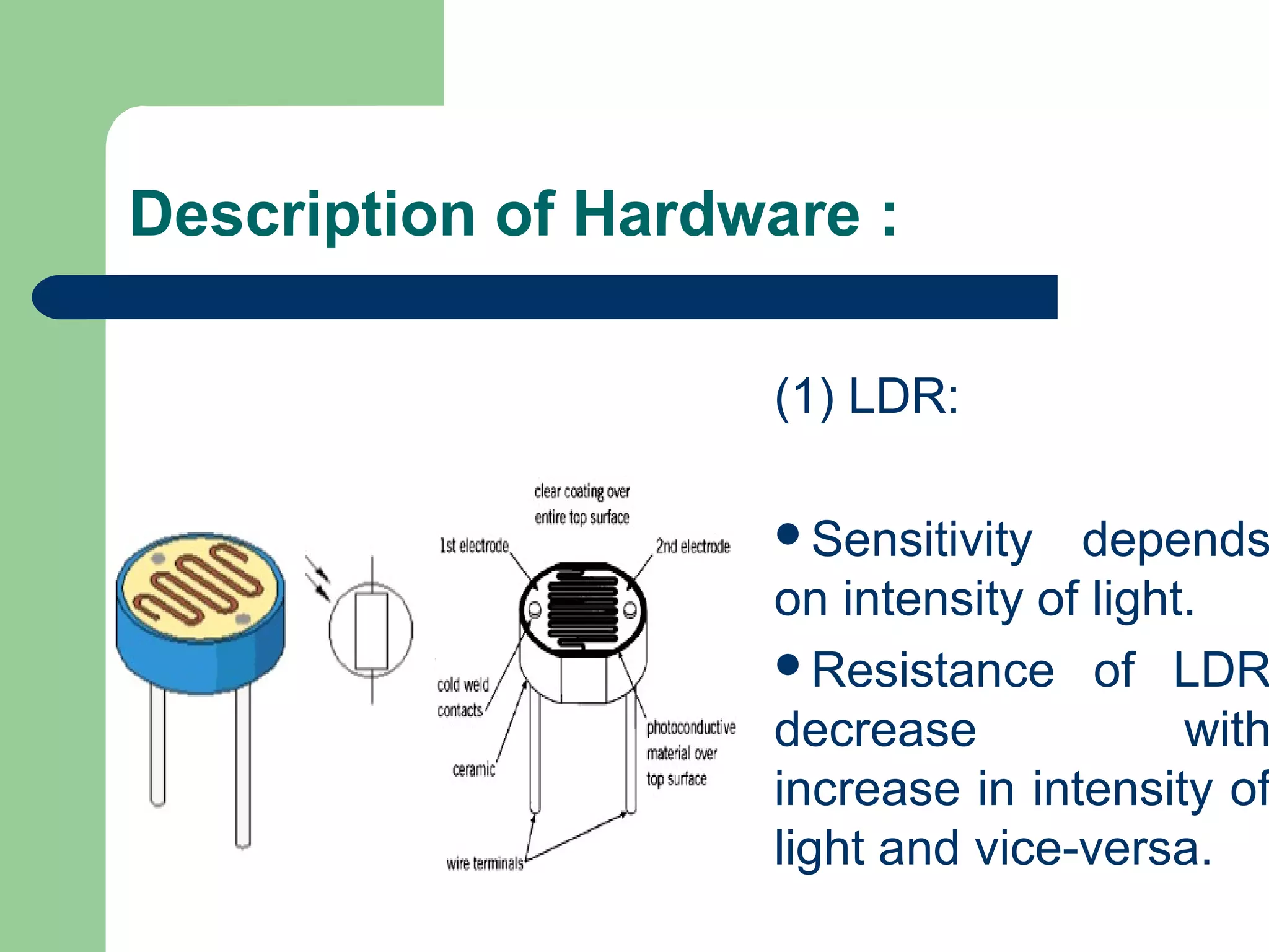


The document describes an automatic street light control system using a light-dependent resistor (LDR) and a simple circuit. The project details its components, working principles, and advantages in energy efficiency, aiming to reduce electricity wastage in street lighting. The system automatically activates street lights based on ambient light conditions, making it a practical solution for modern urban environments.


![ANPARA THERMAL POWER STATION[1] sangam.pdf](https://cdn.slidesharecdn.com/ss_thumbnails/anparathermalpowerstation1sangam-251121115219-9261cde4-thumbnail.jpg?width=640&height=640&fit=bounds)


