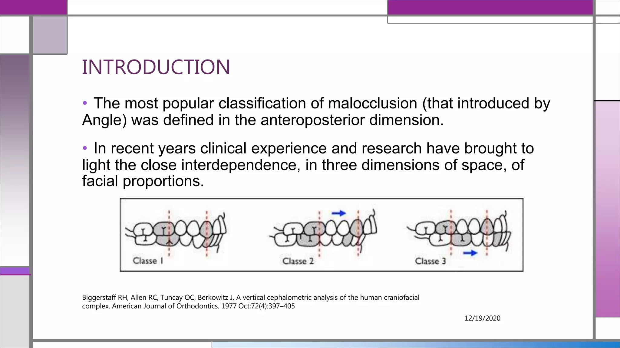
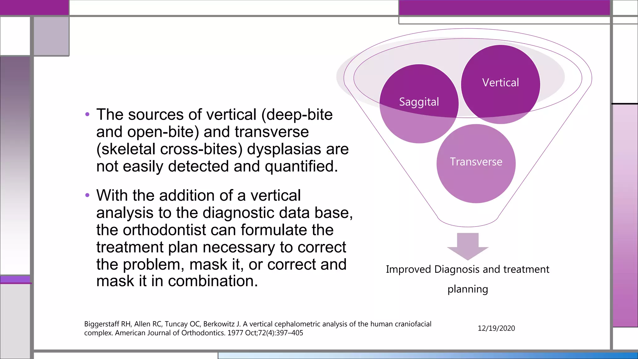
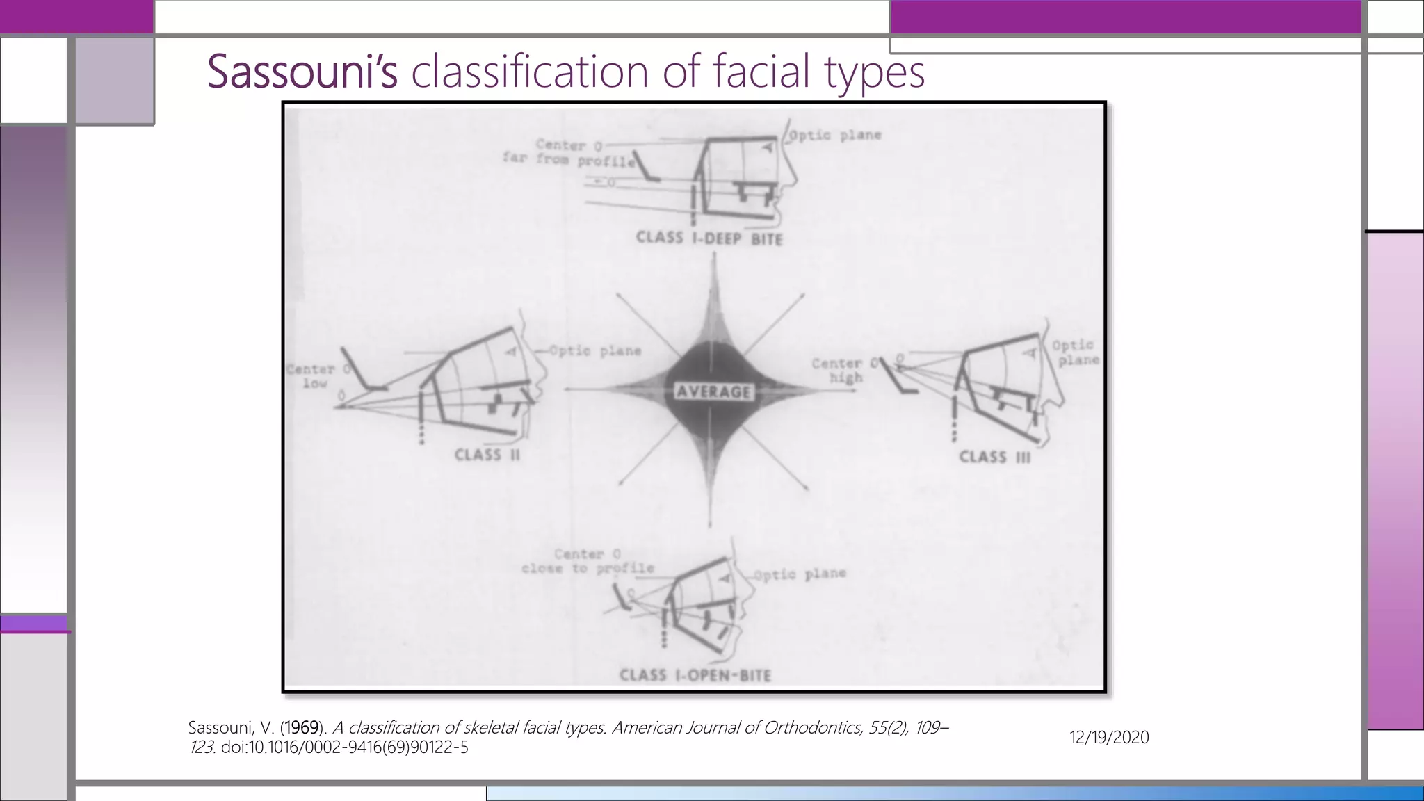
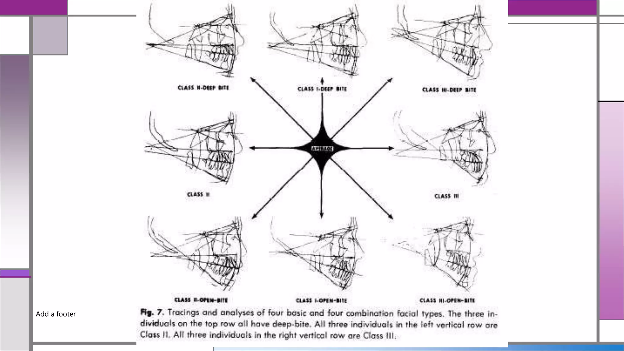
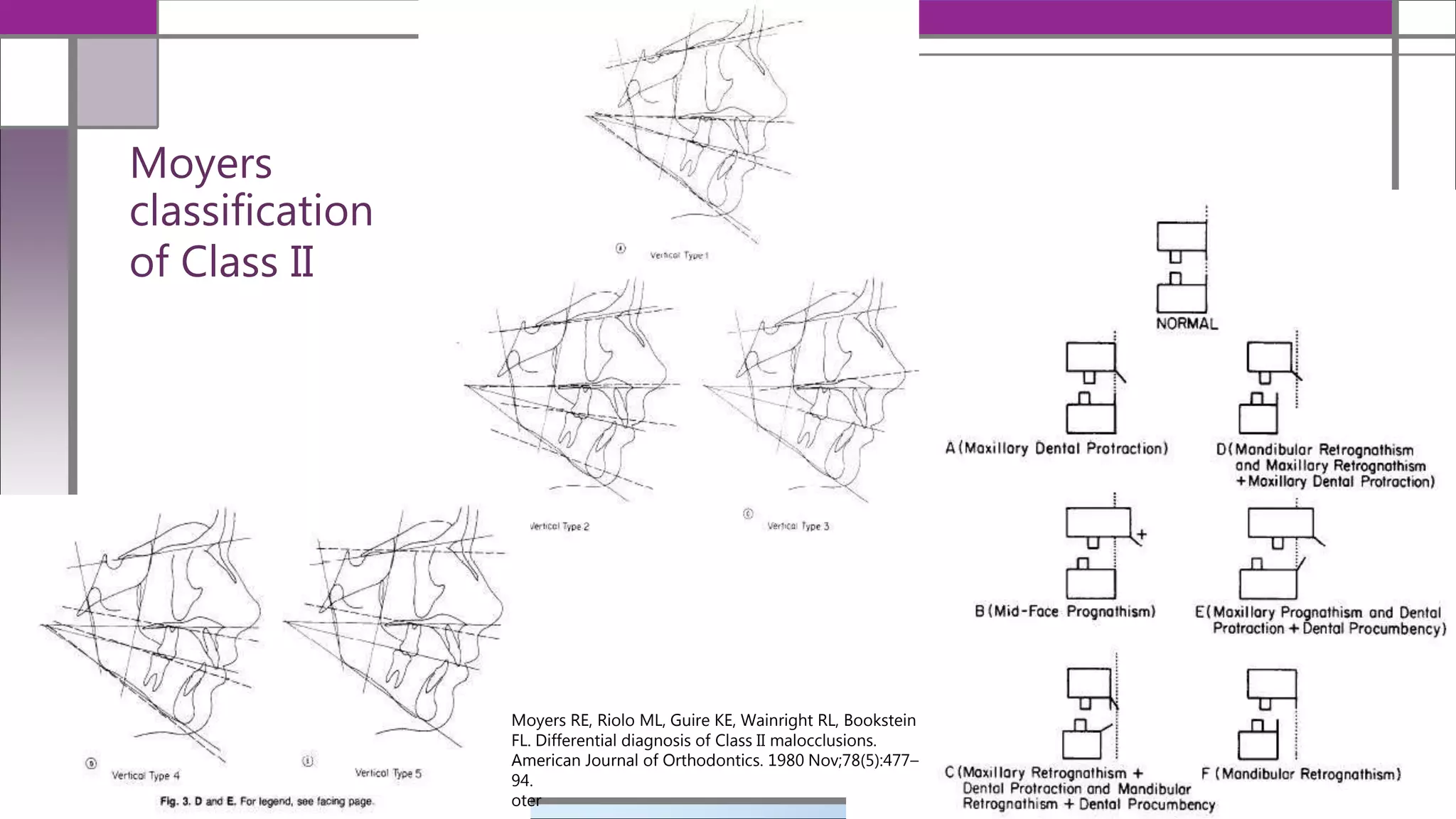
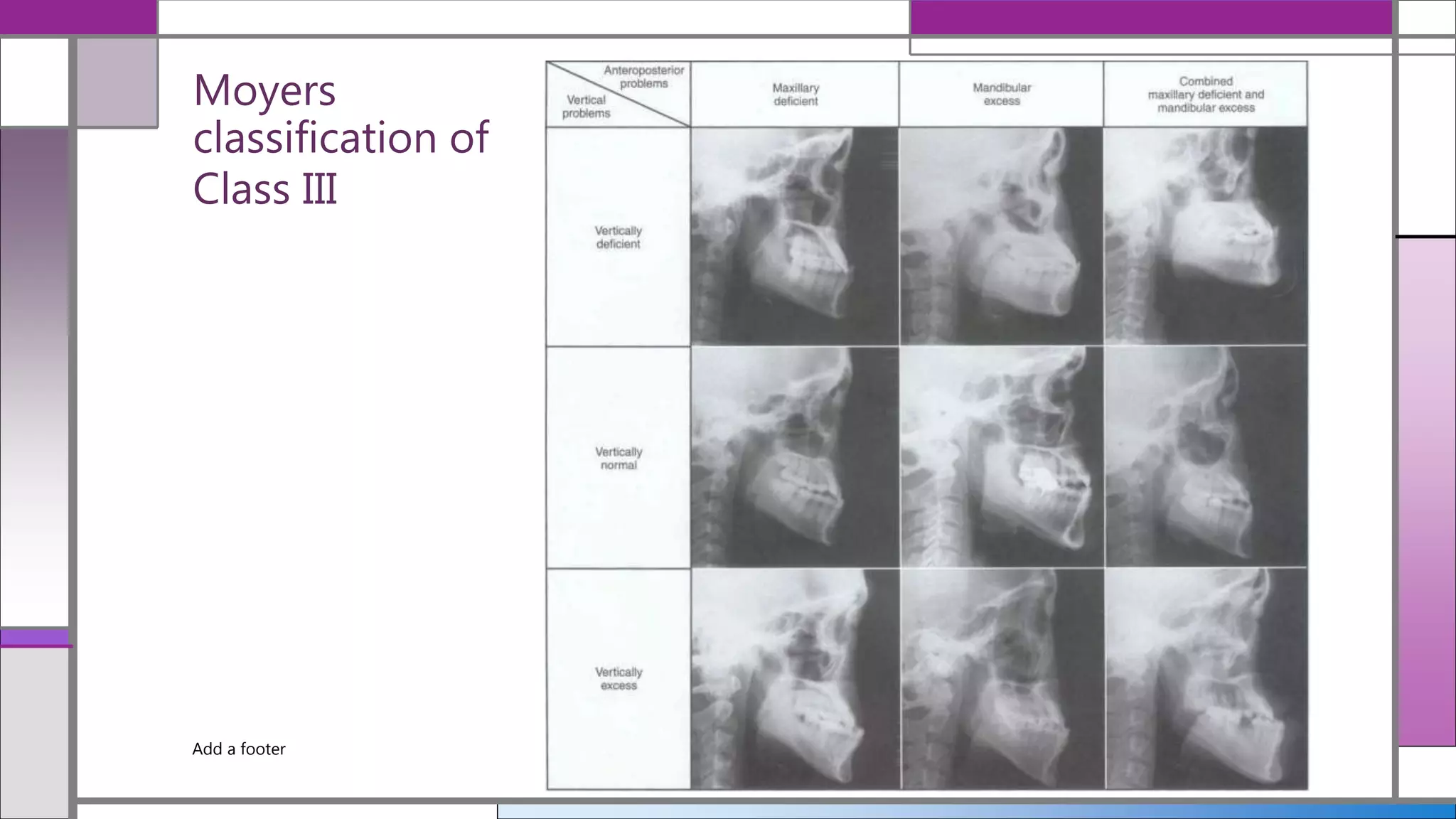
Cephalometric
analysis of vertical
parameters
Dr. Shriya P. Murarka
12/19/2020Add a footer
Title and Content Layout with List
• Introduction
• Sassouni’s classification of facial types
• Moyer’s classification of malocclusion
• Vertical maxillary excess
• Composite analysis of vertical Parameters
• Sassouni’s Analysis
• Di Paolo Quadrilateral analysis 1984
• Centographic analysis
• Conclusion
• References
12/19/2020Add a footer
INTRODUCTION
• The most popular classification of malocclusion (that introduced by
Angle) was defined in the anteroposterior dimension.
• In recent years clinical experience and research have brought to
light the close interdependence, in three dimensions of space, of
facial proportions.
12/19/2020
Biggerstaff RH, Allen RC, Tuncay OC, Berkowitz J. A vertical cephalometric analysis of the human craniofacial
complex. American Journal of Orthodontics. 1977 Oct;72(4):397–405
• The sources of vertical (deep-bite
and open-bite) and transverse
(skeletal cross-bites) dysplasias are
not easily detected and quantified.
• With the addition of a vertical
analysis to the diagnostic data base,
the orthodontist can formulate the
treatment plan necessary to correct
the problem, mask it, or correct and
mask it in combination.
12/19/2020
Biggerstaff RH, Allen RC, Tuncay OC, Berkowitz J. A vertical cephalometric analysis of the human craniofacial
complex. American Journal of Orthodontics. 1977 Oct;72(4):397–405
Improved Diagnosis and treatment
planning
Transverse
Saggital
Vertical
Sassouni’s classification of facial types
Sassouni, V. (1969). A classification of skeletal facial types. American Journal of Orthodontics, 55(2), 109–
123. doi:10.1016/0002-9416(69)90122-5
12/19/2020
12/19/2020
Add a footer
Moyers
classification
of Class II
12/19/2020
Moyers RE, Riolo ML, Guire KE, Wainright RL, Bookstein
FL. Differential diagnosis of Class II malocclusions.
American Journal of Orthodontics. 1980 Nov;78(5):477–
94.
oter
Moyers
classification of
Class III
Add a footer 12/19/2020
Long face Syndrome/ Vertical Maxillary Excess
1.
Schendel SA, Eisenfeld J, Bell WH, Epker BN, Mishelevich DJ. The long face syndrome: Vertical maxillary
excess. American Journal of Orthodontics. 1976 Oct;70(4):398–408.
12/19/2020
A clinically recognizable facial morphology, the long
face syndrome, is manifested primarily by
excessive lower vertical facial height.
Although this dysmorphology has been most
commonly classified as a skeletal type of open-bite,
it is apparent that the syndrome has been
discussed under numerous other titles.
12/19/2020
Cephalograms of patients clinically diagnosed as having
the long face syndrome were analyzed .Certain typical
cephalometric features were identified :
1. The total anterior face height was increased,
specifically, the lower face height.
2. The increased face height correlated with excess
development of the maxilla in a vertical direction.
3. Open-bite and non-open-bite are two variants of the
long face syndrome.
(A) A normal ramus height existed in the open-bite
patients.
(B)An increased ramus height was seen in non-open-bite
patients.
4. A high mandibular plane angle was characteristic of
both groups.
5. A normal upper lip length with an excess display of the
anterior maxillary teeth was found in both study groups.
Variations of VME
1.
Schendel SA, Carlotti AE. Variations of total vertical maxillary excess. Journal of Oral and Maxillofacial
Surgery. 1985 Aug;43(8):590–6.
12/19/2020
FIGURE 2 Total maxillary excess group: the vertical
maxillary excess and vertical chin excess present are
shown by the shaded areas. A Class II malocclusion
secondary to mandibular deficiency was also present
in this group.
FIGURE 3 Short lip group. This group, while
displaying an excessive amount of incisor, actually
had a deficiency of soft tissue. Confusing the picture
and giving the appearance of a long face was vertical
chin excess (shaded area) and a Class II malocclusion.
The mandibular deficiency was partly compensated
by a forward position of the glenoid fossa.
Add a footer
12/19/2020
FIGURE 4. Total maxillary excess with premaxillary abasement. This group had
vertical maxillary excess and chin excess, as shown by the shading. However, the
anterior excess was exaggerated by a lowering of total premaxillary segment from
the ideal position. The mandibular deficiency was compensated by a forward,
inferior position of the glenoid fossa.
FIGURE 5 Maxillary excess with palatal rotation. This group had maxillary
vertical excess and a clockwise rotation of the total palate-premaxillary complex.
The counter-clockwise rotation is shown here. Vertical chin excess and
mandibular deficiency are also seen in these patients.
12/19/2020
FIGURE 6 Maxillary excess with abasement of the posterior palate. This group was characterized by
vertical maxillary excess and lowering of the posterior palate. In the example shown, chin excess and a
Class II malocclusion are also present. Shaded areas represent areas of excess.
FIGURE 7Maxillary excess with premaxillary elevation. In this group. posterior vertical maxillary excess is
greatest because the premaxillary segment is generally rotated superiorly. resulting in a normal lip-to-
tooth relationship. Open bite is frequently present, as is vertical chin excess. Areas of excess are shaded
and the premaxillary elevation is marked by cross lining.
Add a footer
COMPOSITE ANALYSIS
GROWTH PATTERN
Measurements Mean value Inference Analysis
Go-Gn to SN 32 ̊ Steiner’s
Mandibular palne angle 21.9 ̊̊ Down’s
FMPA 25 ̊̊ Tweed’s
Y- Axis 59 ̊̊ Down’s
Facial axis angle 90 ̊ Rickett’s
Jarabak’s Ratio 60-65 ̊ Rakosi Jarabak
Articular angle 143±6 ̊̊ Rakosi
Gonial angle 128±7 ̊ Rakosi
Upper gonial angle 52-55 ̊ Rakosi
Lower gonial angle 72-75 ̊̊ Rakosi 12/19/2020Add a footer
COMPOSITE ANALYSIS
POSITION OF MOLARS
Measurements Mean value Analysis
U6 To NF 26.2-23 mm Burstone
L6 to MP 35-32 mm Burstone
12/19/2020Add a footer
COMPOSITE ANALYSIS
OCCLUSAL PLANE
Measurements Mean value Analysis
Occlusal plane to SN 14 ̊ Steiner’s
Cant of Occlusal plane 9.3 ̊̊ Down’s
Pn to Occlusal plane 75 ̊ Rakosi
Palatal to Occlusal plane 110 ̊ Rakosi
Occlusal to mandibular
plane
14 ̊ Rakosi
Basal plane angle 25 ̊ Rakosi
12/19/2020Add a footer
396+/-60
122+144+130=396+/-60
Given by Bjork
>3960 –vertical growth
<3960 –Horizontal
growth
Sum of Posterior Angles
• An Atlas and Manual of Cephalometric Radiography; T. Rakosi, Wolfe Medical Publications.
Bjork (1947)
12/19/2020Add a footer
Add a footer 12/19/2020
Anterior face height- N-Me
Posterior face height- S-GO
Post face height X100 = 62-65%
Anterior face Height
Anterior and Posterior face
Height
• Dentofacial Orthopaedics WITH FUNCTIONAL APPLIANCES; t.m. Graber, Rakosi, A.P. Petrovic,2nd edition,
12/19/2020Add a footer
Add a footer 12/19/2020
Sassouni analysis (1955)
A ROENTGENOGRAPHIC CEPHALOMETRIC SNALYSIS OF
CEPHALO-FACIO-DENTAL RELATIONSHIPS
PIKEN SASSOUNI; 1955
12/19/2020
Anterior Arc.-The arc of a circle, between anterior cranial
base plane and mandibular plane, with 0 as center and 0-
ANS as radius.
Posterior Arc.-The arc of a circle, between anterior cranial
base planeand mandibular base plane, with 0 as center
and OSp as radius.
(Sp is the most posterior point on the rear margin of sella
turcica.)
Add a footer 12/19/2020
Vertical Proportions.-comparison of lower face (below the palatal plane) to upper
face.
I. Equal: The distance from ANS to the mandibular plane is equal
to the distance from ANS to the cranial base plane, on the arc
II. Minus: Where the lower face is smaller than the upper face (Fig.
III. Plus: Where the lower face is larger than the upper face
The classification is based on ANS for the anterior face and PNS for the
posterior face.
Add a footer 12/19/2020
The quadrilateral analysis 1984
Di Paolo, R. J., Philip, C., Maganzini, A. L., & Hirce, J. D. (1984). The quadrilateral analysis:
A differential diagnosis for surgical orthodontics. American Journal of Orthodontics,
86(6), 470–482. doi:10.1016/s0002-9416(84)90353-1
12/19/2020
The quadrilateral
analysis indicates that in a balanced facial pattern
a 1: 1 ratio exists between the maxillary bony base
length (Max.Lth.) and the mandibular bony base
length (Mand.Lth.);
the average of the anterior lower
facial height (ALFH) and posterior lower facial
height (PLFH) equals these bony base lengths. S
the Max.Lth. = Man.Lth. = ALFH ± PLFH
2
Add a footer 12/19/2020
Centographic analysis (1997)
Fishman, L. S. (1997). Individualized evaluation of facial form. American Journal of Orthodontics and
Dentofacial Orthopedics, 111(5), 510–517. doi:10.1016/s0889-5406(97)70288-9
12/19/2020
A centroid represents the center of mass or
gravity of a two-dimensional area or a three-
dimensional volume.
The most convenient centroid construction
method for a triangle involves the intersection of
two or three planes derived by connecting a
triangular vertex to the midpoint of the opposing
side.
An important characteristic of centroids is that
they change minimally in position as a triangle
increases in size and shape. Points located on
the periphery of an enlarged area, such as
traditionally used cephalometric landmarks, alter
positionally more than their representative
centroids.
Add a footer 12/19/2020
Cephalomorphic is a more appropriate term than
cephalometric to use, as it implies a
nonnumerical analysis of morphologic shape
and position.
Add a footer 12/19/2020
harmonious
Upper centroid
discrepancy
Lower centroid
discrepancy
Conclusion
Add a footer 12/19/2020
To have a meaningful value for clinical purposes, a cephalometric analysis must
combine the basic knowledge of facial architecture with the functional components
of the masticatory apparatus, with the genetic growth potential, and with the
possibilities and limitations of orthodontic treatment, but at the same time it must
not exclude esthetic and social considerations.
• 1. Sassouni V, Nanda S. Analysis of dentofacial vertical proportions. American Journal of
Orthodontics. 1964 Nov;50(11):801–23.
• 2. Sassouni and Nanda - 1964 - Analysis of dentofacial vertical proportions.pdf.
• 3. Felicita As, Chandrasekar S, Shanthasundari K. Determination of craniofacial relation among
the subethnic Indian population: A modified approach (vertical evaluation). Indian Journal of
Dental Research. 2013;24(4):456.
• 4. Bock JJ, Fuhrmann RAW. Evaluation of Vertical Parameters in Cephalometry. Journal of
Orofacial Orthopedics / Fortschritte der Kieferorthopädie. 2007 May;68(3):210–22.
• 5. Biggerstaff RH, Allen RC, Tuncay OC, Berkowitz J. A vertical cephalometric analysis of the
human craniofacial complex. American Journal of Orthodontics. 1977 Oct;72(4):397–405.
• 6. Ahmed M, Shaikh A, Fida M. Diagnostic performance of various cephalometric parameters
for the assessment of vertical growth pattern. Dental Press Journal of Orthodontics. 2016
Aug;21(4):41–9.
Add a footer 12/19/2020
THANKYOU
Add a footer 12/19/2020

Cephalometric Analysis of discrepancy in Vertical plane

  • 1.
    Cephalometric analysis of vertical parameters Dr.Shriya P. Murarka 12/19/2020Add a footer
  • 2.
    Title and ContentLayout with List • Introduction • Sassouni’s classification of facial types • Moyer’s classification of malocclusion • Vertical maxillary excess • Composite analysis of vertical Parameters • Sassouni’s Analysis • Di Paolo Quadrilateral analysis 1984 • Centographic analysis • Conclusion • References 12/19/2020Add a footer
  • 3.
    INTRODUCTION • The mostpopular classification of malocclusion (that introduced by Angle) was defined in the anteroposterior dimension. • In recent years clinical experience and research have brought to light the close interdependence, in three dimensions of space, of facial proportions. 12/19/2020 Biggerstaff RH, Allen RC, Tuncay OC, Berkowitz J. A vertical cephalometric analysis of the human craniofacial complex. American Journal of Orthodontics. 1977 Oct;72(4):397–405
  • 4.
    • The sourcesof vertical (deep-bite and open-bite) and transverse (skeletal cross-bites) dysplasias are not easily detected and quantified. • With the addition of a vertical analysis to the diagnostic data base, the orthodontist can formulate the treatment plan necessary to correct the problem, mask it, or correct and mask it in combination. 12/19/2020 Biggerstaff RH, Allen RC, Tuncay OC, Berkowitz J. A vertical cephalometric analysis of the human craniofacial complex. American Journal of Orthodontics. 1977 Oct;72(4):397–405 Improved Diagnosis and treatment planning Transverse Saggital Vertical
  • 5.
    Sassouni’s classification offacial types Sassouni, V. (1969). A classification of skeletal facial types. American Journal of Orthodontics, 55(2), 109– 123. doi:10.1016/0002-9416(69)90122-5 12/19/2020
  • 6.
  • 7.
    Moyers classification of Class II 12/19/2020 MoyersRE, Riolo ML, Guire KE, Wainright RL, Bookstein FL. Differential diagnosis of Class II malocclusions. American Journal of Orthodontics. 1980 Nov;78(5):477– 94. oter
  • 8.
  • 9.
    Long face Syndrome/Vertical Maxillary Excess 1. Schendel SA, Eisenfeld J, Bell WH, Epker BN, Mishelevich DJ. The long face syndrome: Vertical maxillary excess. American Journal of Orthodontics. 1976 Oct;70(4):398–408. 12/19/2020 A clinically recognizable facial morphology, the long face syndrome, is manifested primarily by excessive lower vertical facial height. Although this dysmorphology has been most commonly classified as a skeletal type of open-bite, it is apparent that the syndrome has been discussed under numerous other titles.
  • 10.
    12/19/2020 Cephalograms of patientsclinically diagnosed as having the long face syndrome were analyzed .Certain typical cephalometric features were identified : 1. The total anterior face height was increased, specifically, the lower face height. 2. The increased face height correlated with excess development of the maxilla in a vertical direction. 3. Open-bite and non-open-bite are two variants of the long face syndrome. (A) A normal ramus height existed in the open-bite patients. (B)An increased ramus height was seen in non-open-bite patients. 4. A high mandibular plane angle was characteristic of both groups. 5. A normal upper lip length with an excess display of the anterior maxillary teeth was found in both study groups.
  • 11.
    Variations of VME 1. SchendelSA, Carlotti AE. Variations of total vertical maxillary excess. Journal of Oral and Maxillofacial Surgery. 1985 Aug;43(8):590–6. 12/19/2020 FIGURE 2 Total maxillary excess group: the vertical maxillary excess and vertical chin excess present are shown by the shaded areas. A Class II malocclusion secondary to mandibular deficiency was also present in this group. FIGURE 3 Short lip group. This group, while displaying an excessive amount of incisor, actually had a deficiency of soft tissue. Confusing the picture and giving the appearance of a long face was vertical chin excess (shaded area) and a Class II malocclusion. The mandibular deficiency was partly compensated by a forward position of the glenoid fossa.
  • 12.
    Add a footer 12/19/2020 FIGURE4. Total maxillary excess with premaxillary abasement. This group had vertical maxillary excess and chin excess, as shown by the shading. However, the anterior excess was exaggerated by a lowering of total premaxillary segment from the ideal position. The mandibular deficiency was compensated by a forward, inferior position of the glenoid fossa. FIGURE 5 Maxillary excess with palatal rotation. This group had maxillary vertical excess and a clockwise rotation of the total palate-premaxillary complex. The counter-clockwise rotation is shown here. Vertical chin excess and mandibular deficiency are also seen in these patients.
  • 13.
    12/19/2020 FIGURE 6 Maxillaryexcess with abasement of the posterior palate. This group was characterized by vertical maxillary excess and lowering of the posterior palate. In the example shown, chin excess and a Class II malocclusion are also present. Shaded areas represent areas of excess. FIGURE 7Maxillary excess with premaxillary elevation. In this group. posterior vertical maxillary excess is greatest because the premaxillary segment is generally rotated superiorly. resulting in a normal lip-to- tooth relationship. Open bite is frequently present, as is vertical chin excess. Areas of excess are shaded and the premaxillary elevation is marked by cross lining. Add a footer
  • 14.
    COMPOSITE ANALYSIS GROWTH PATTERN MeasurementsMean value Inference Analysis Go-Gn to SN 32 ̊ Steiner’s Mandibular palne angle 21.9 ̊̊ Down’s FMPA 25 ̊̊ Tweed’s Y- Axis 59 ̊̊ Down’s Facial axis angle 90 ̊ Rickett’s Jarabak’s Ratio 60-65 ̊ Rakosi Jarabak Articular angle 143±6 ̊̊ Rakosi Gonial angle 128±7 ̊ Rakosi Upper gonial angle 52-55 ̊ Rakosi Lower gonial angle 72-75 ̊̊ Rakosi 12/19/2020Add a footer
  • 15.
    COMPOSITE ANALYSIS POSITION OFMOLARS Measurements Mean value Analysis U6 To NF 26.2-23 mm Burstone L6 to MP 35-32 mm Burstone 12/19/2020Add a footer
  • 16.
    COMPOSITE ANALYSIS OCCLUSAL PLANE MeasurementsMean value Analysis Occlusal plane to SN 14 ̊ Steiner’s Cant of Occlusal plane 9.3 ̊̊ Down’s Pn to Occlusal plane 75 ̊ Rakosi Palatal to Occlusal plane 110 ̊ Rakosi Occlusal to mandibular plane 14 ̊ Rakosi Basal plane angle 25 ̊ Rakosi 12/19/2020Add a footer
  • 17.
    396+/-60 122+144+130=396+/-60 Given by Bjork >3960–vertical growth <3960 –Horizontal growth Sum of Posterior Angles • An Atlas and Manual of Cephalometric Radiography; T. Rakosi, Wolfe Medical Publications. Bjork (1947) 12/19/2020Add a footer
  • 18.
    Add a footer12/19/2020
  • 19.
    Anterior face height-N-Me Posterior face height- S-GO Post face height X100 = 62-65% Anterior face Height Anterior and Posterior face Height • Dentofacial Orthopaedics WITH FUNCTIONAL APPLIANCES; t.m. Graber, Rakosi, A.P. Petrovic,2nd edition, 12/19/2020Add a footer
  • 20.
    Add a footer12/19/2020
  • 21.
    Add a footer12/19/2020
  • 22.
    Sassouni analysis (1955) AROENTGENOGRAPHIC CEPHALOMETRIC SNALYSIS OF CEPHALO-FACIO-DENTAL RELATIONSHIPS PIKEN SASSOUNI; 1955 12/19/2020 Anterior Arc.-The arc of a circle, between anterior cranial base plane and mandibular plane, with 0 as center and 0- ANS as radius. Posterior Arc.-The arc of a circle, between anterior cranial base planeand mandibular base plane, with 0 as center and OSp as radius. (Sp is the most posterior point on the rear margin of sella turcica.)
  • 23.
    Add a footer12/19/2020 Vertical Proportions.-comparison of lower face (below the palatal plane) to upper face. I. Equal: The distance from ANS to the mandibular plane is equal to the distance from ANS to the cranial base plane, on the arc II. Minus: Where the lower face is smaller than the upper face (Fig. III. Plus: Where the lower face is larger than the upper face The classification is based on ANS for the anterior face and PNS for the posterior face.
  • 24.
    Add a footer12/19/2020
  • 25.
    The quadrilateral analysis1984 Di Paolo, R. J., Philip, C., Maganzini, A. L., & Hirce, J. D. (1984). The quadrilateral analysis: A differential diagnosis for surgical orthodontics. American Journal of Orthodontics, 86(6), 470–482. doi:10.1016/s0002-9416(84)90353-1 12/19/2020 The quadrilateral analysis indicates that in a balanced facial pattern a 1: 1 ratio exists between the maxillary bony base length (Max.Lth.) and the mandibular bony base length (Mand.Lth.); the average of the anterior lower facial height (ALFH) and posterior lower facial height (PLFH) equals these bony base lengths. S the Max.Lth. = Man.Lth. = ALFH ± PLFH 2
  • 26.
    Add a footer12/19/2020
  • 27.
    Add a footer12/19/2020
  • 28.
    Add a footer12/19/2020
  • 29.
    Add a footer12/19/2020
  • 30.
    Centographic analysis (1997) Fishman,L. S. (1997). Individualized evaluation of facial form. American Journal of Orthodontics and Dentofacial Orthopedics, 111(5), 510–517. doi:10.1016/s0889-5406(97)70288-9 12/19/2020 A centroid represents the center of mass or gravity of a two-dimensional area or a three- dimensional volume. The most convenient centroid construction method for a triangle involves the intersection of two or three planes derived by connecting a triangular vertex to the midpoint of the opposing side. An important characteristic of centroids is that they change minimally in position as a triangle increases in size and shape. Points located on the periphery of an enlarged area, such as traditionally used cephalometric landmarks, alter positionally more than their representative centroids.
  • 31.
    Add a footer12/19/2020
  • 32.
    Add a footer12/19/2020 Cephalomorphic is a more appropriate term than cephalometric to use, as it implies a nonnumerical analysis of morphologic shape and position.
  • 33.
    Add a footer12/19/2020 harmonious Upper centroid discrepancy Lower centroid discrepancy
  • 34.
    Conclusion Add a footer12/19/2020 To have a meaningful value for clinical purposes, a cephalometric analysis must combine the basic knowledge of facial architecture with the functional components of the masticatory apparatus, with the genetic growth potential, and with the possibilities and limitations of orthodontic treatment, but at the same time it must not exclude esthetic and social considerations.
  • 35.
    • 1. SassouniV, Nanda S. Analysis of dentofacial vertical proportions. American Journal of Orthodontics. 1964 Nov;50(11):801–23. • 2. Sassouni and Nanda - 1964 - Analysis of dentofacial vertical proportions.pdf. • 3. Felicita As, Chandrasekar S, Shanthasundari K. Determination of craniofacial relation among the subethnic Indian population: A modified approach (vertical evaluation). Indian Journal of Dental Research. 2013;24(4):456. • 4. Bock JJ, Fuhrmann RAW. Evaluation of Vertical Parameters in Cephalometry. Journal of Orofacial Orthopedics / Fortschritte der Kieferorthopädie. 2007 May;68(3):210–22. • 5. Biggerstaff RH, Allen RC, Tuncay OC, Berkowitz J. A vertical cephalometric analysis of the human craniofacial complex. American Journal of Orthodontics. 1977 Oct;72(4):397–405. • 6. Ahmed M, Shaikh A, Fida M. Diagnostic performance of various cephalometric parameters for the assessment of vertical growth pattern. Dental Press Journal of Orthodontics. 2016 Aug;21(4):41–9. Add a footer 12/19/2020
  • 36.

Editor's Notes

  • #3 As you all know we are continuing with series of seminars on cephalometrics today I ll b speaking on vertical parameters
  • #4 It was angles era back then in 19th century. And when he putforth his classification it was only the saggital plane that was been taken into consideration
  • #5 After 1st ;line: Yet the clinician often requires this information in treatment planning to pinpoint the areas of disharmony.
  • #8 Steep mandibularplane long face syndrome Square face . Orientations of planes almost parallel 3. skeletal anterior open bite, divergent jaw bases Type 4 is rare and severe. Maxillary and mandibular plane tippeddownwards. Incisors prolined Similar to type 2.more squarre face more severe leadsto skeletal deep bite
  • #10  Extreme clockwise rotation, high angle type, adenoid faces, idiopathic long face, total maxillary alveolar hyperplasia, and vertical maxillary excess all have excessive vertical growth of the maxilla as their common denominator.14
  • #11 Superimposition of the facial polygons. Solid line represents the open-bite polygon and dotted line represents the non-open-bite polygon. facial height (PFH); the average open-bite group was 72.87 mm., compared to the non-open-bite group average of 80.13 mm. The ramus height of the open-bite group (54.53 mm.) was essentially normal (56.30 mm.), while the ramus height of the non-open-bite group was long (60.88 mm.). The posterior height of the maxilla (OP-PP) was
  • #18 Bjorks polygon
  • #20 Posterior face heights in the longitudinal study of 9-year- old children with horizontal growth patterns were longer on average (69.5 mm) than they were in children with vertical growth patterns (64.1 mm). A ratio of less than 62% expresses a vertical growth pattern, whereas a ratio of more than 65 % increases the likeli- hood for a horizontal vector. At 9 years the average ratio in the horizontally growing group was 67.5 %, increasing to 69.9% by 15 years. In the vertically growing group the posterior to anterior face height ratio was 60.1% at 9 years. increasing to 62.7% by 15 years.
  • #23 The aim of this study was to try to find some acceptably constant relat,ion ships in the architecture of the head and to use them for diagnost,ic and trealment purposes in orthodontics.
  • #25 Vertical Proportions.-comparison of lower face (below the palatal plane) to upper face. I. Equal: The distance from ANS to the mandibular plane is equal to the distance from ANS to the cranial base plane, on the arc II. Minus: Where the lower face is smaller than the upper face (Fig. III. Plus: Where the lower face is larger than the upper face The classification is based on ANS for the anterior face and PNS for the posterior face.
  • #28 The quadrilateral analysis indicated a 7 mm discrepancy of the maxillary and mandibular bony base lengths (47 mm = 54 mm). If the mandibular bony base length were reduced 7 mm, the average of the ALFH and PLFH would be not proportional but excessive (47 mm = 54 mm - 7 mm = p46). + 68 This indicated that we were dealing with an 2 anteroposterior and vertical skeletal discrepancy (Fig. 9). These findings should significantly influence our surgical approach. If we were to perform a vertical ostectomy or sagittal split and maintain the occlusal and mandibular plane angles, an anteroposterior reduction would be achieved but an anterior open bite would occur (Fig. 10). The plan of treatment consisted of presurgical orthodontic correction. Mandibular first premolars were removed and a 7 mm subapical reduction was performed. This developed an anteroposterior bony arch balance and created a chin that was in balance with the lower incisor position. The angle of facial convexity was improved to 169” (Figs. 11 and 12).
  • #31 Applying these principles very superficially to facial form, as seen in Fig. 3, if two adjacent triangles representing the upper face (Ba-Na-A) and lower face (Ba-A-Gn) are equal in size and share the two common borders (Ba-A and Na-Gn), the two centroids representing the smaller triangle and centroid representing the larger combined triangle are all positioned along a common centroid plane that is perpendicular to Ba-A. The centroid representing the total face (Na-Ba-Gn) is positioned on the common side (Ba-A
  • #33 good vertical skeletal harmony is associated with the FC being located directly on the Ba-A plane, the constructed division between the upper and lower faces. A deficiency in vertical development of the lower face is depicted by the FC being positioned within the upper face. An excessive amount of lower facial development is depicted by the FC being positioned within the lower face
  • #34 horizontal skeletal imbalance, whereby the upper face is positioned too far forward relative to the lower face, is depicted by the UC being located in front of the centroid plane. The upper facial area being positioned too far posteriorly is depicted by the posterior location of the UC to the centroid plane (F an excessive amount of forward skeletal development of the lower face is depicted by the LC being located anterior to the centroid plane. A deficiency in horizontal development of the lower face is depicted by the LC being positioned posterior to the centroid plane