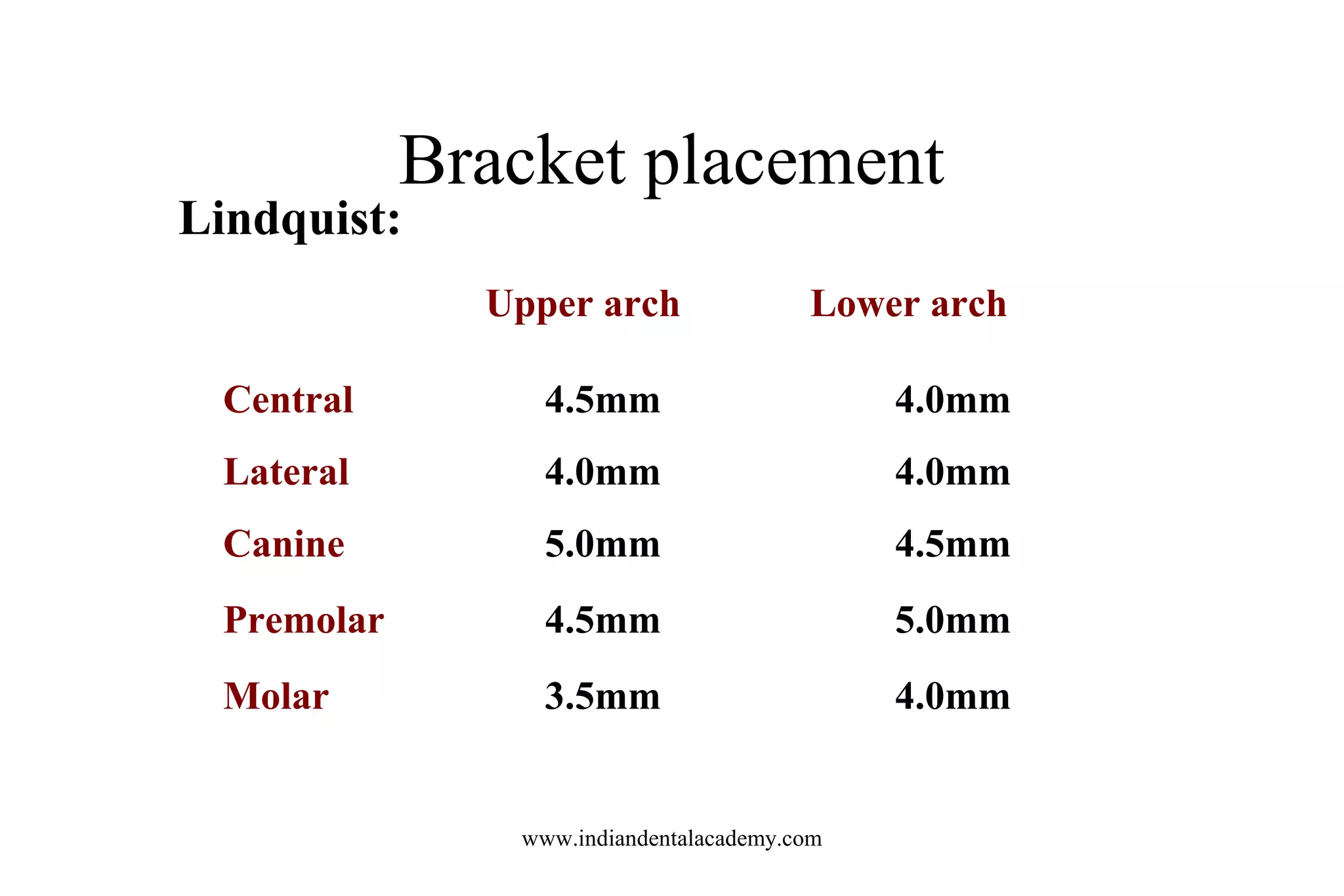
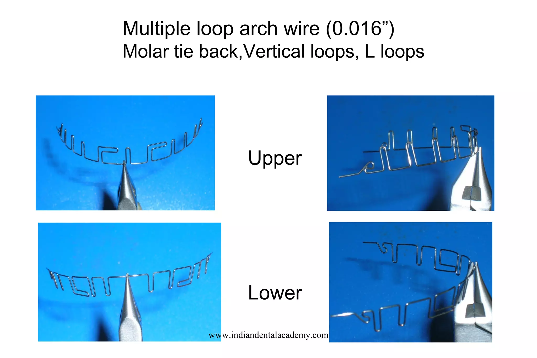
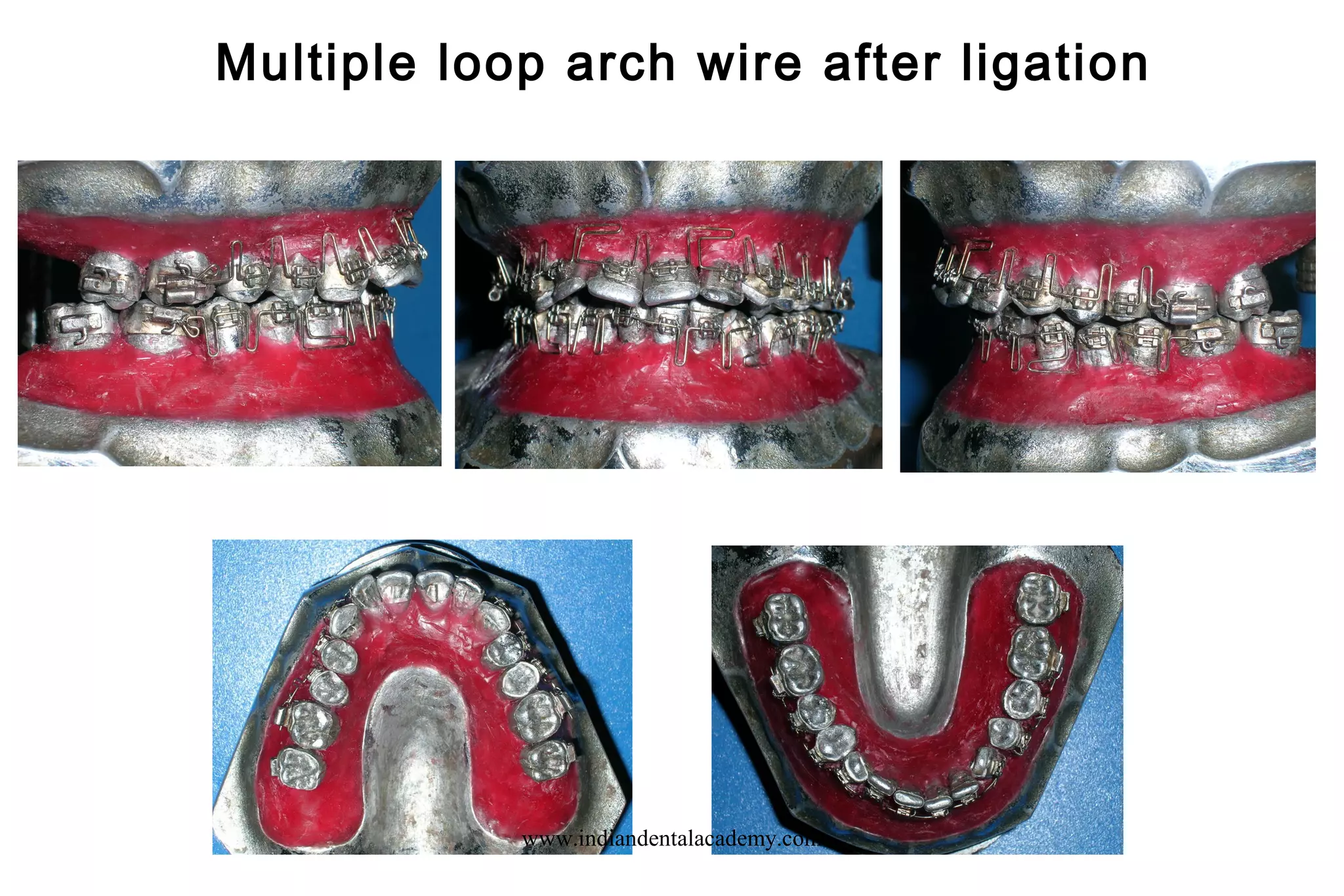
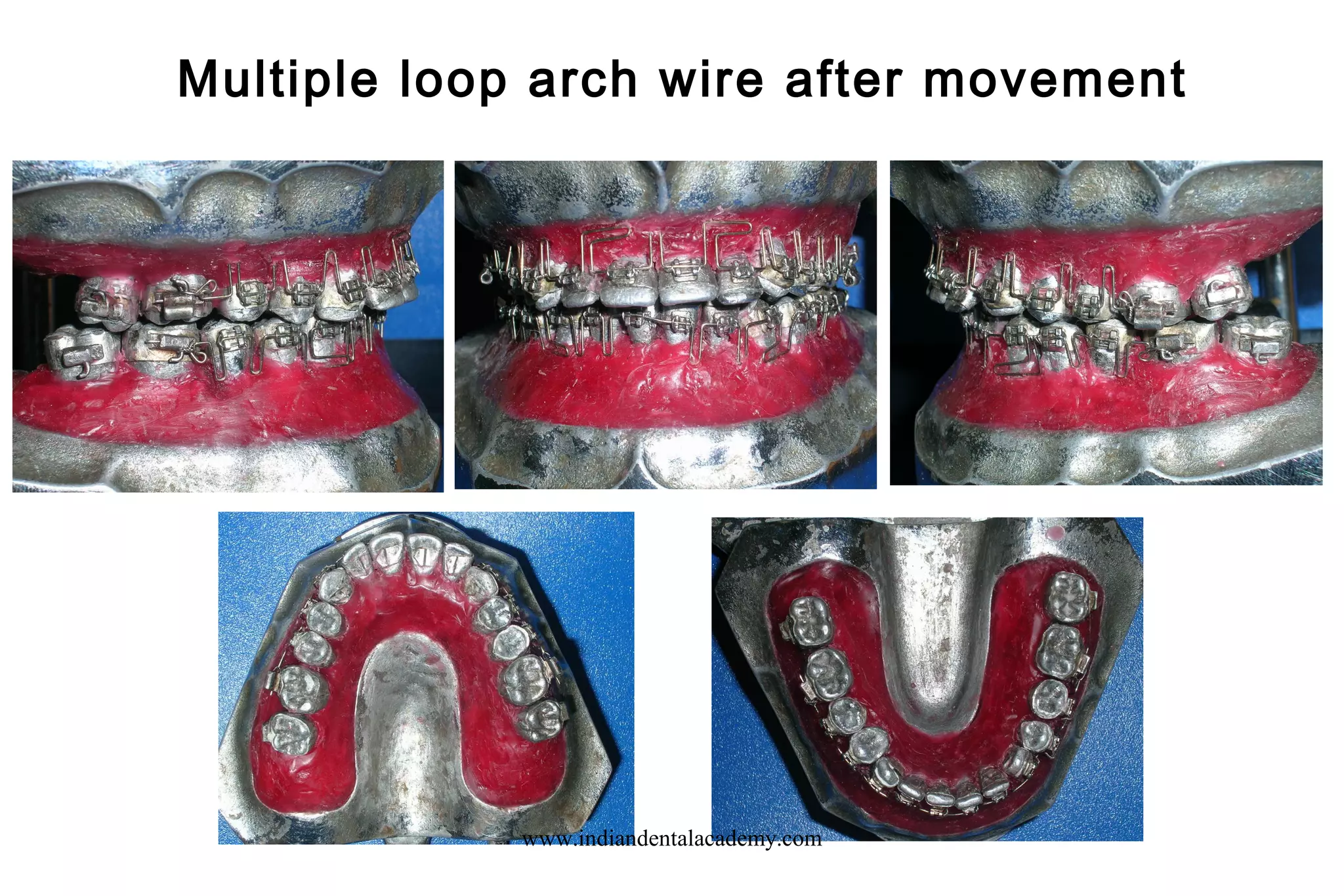
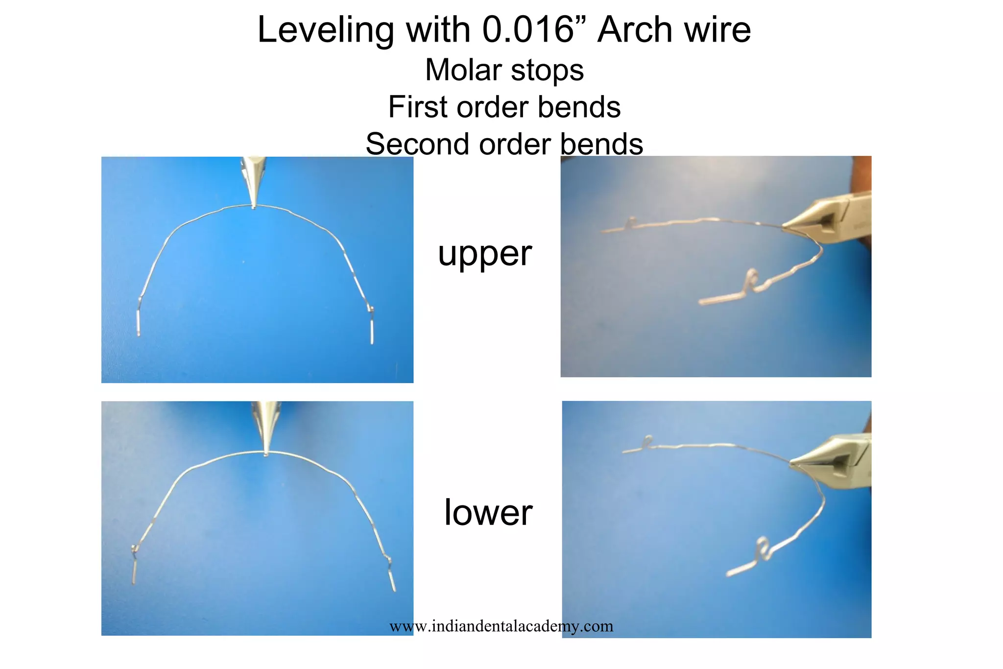
Bracket Positioning,
Sequence of Mechanics
in
Edgewise Mechanics
www.indiandentalacademy.com
Basics of Edgewise
www.indiandentalacademy.com
Growth trends
– Type A growth trend
– Type B growth trend
– Type C growth trend
www.indiandentalacademy.com
Type A growth trend
• The middle and lower face are growing forward and
downward in unison, with no change in size of the ANB
• Growth is approximately equal in both the vertical and
horizontal dimensions
• Approximately 25 % of patients
www.indiandentalacademy.com
Type B growth trend
• Growth downward and forward with the middle face
growing forward more rapidly than the lower face
• Growth of the middle and lower face is predominantly in the
vertical dimension in most instances
• ANB reading 60
to 120
• If ANB is less than 40
prognosis is fair
• If ANB is 70
to 120
prognosis is poor
• Extraction of all four first premolar mandatory for patients
with high ANB angle
• Only about 15% patientswww.indiandentalacademy.com
Type C growth trend
• Lower face is growing downward and forward more rapidly than
the middle face with a decreases in ANB angle
• When FMA ranges upward from 200
, growth is approximately
equal in the vertical and horizontal dimensions
• When FMA 200
or less, growth predominantly horizontal
• When growth is virtually confined to the horizontal dimension
with little vertical growth, the growth trend is classified as Type C
subdivision.
• 60% patients have Type C growth trend
www.indiandentalacademy.com
Anchorage
• Tooth anchorage (Anchorage preparation)
• Anchorage savers
Anchorage preparation
• 1st
degree
• 2nd
degree
• 3rd
degree
Anchorage savers
• Headgear or palatal bar
• Nance button
• Delayed extraction
• Lip bumpers
• Muscular pattern of low FMA cases
www.indiandentalacademy.com
Bracket placement
• Precision bracket placement is essential for good leveling
and alignment.
• Indirect bonding showed better bracket placement. (Koo,
Chung, Vanarsdall, 1999)
• Light cure bonding also showed better bracket placement
than chemical cure.
• Bonding with orthocad technology shows more accurate
bracket positioning.
www.indiandentalacademy.com
Bracket placement
Tweed: Mandibular arch:
• Bracket slot should be 3.5mm from incisal edge or cuspal tip
• On molars -Between occlusal and middle third
Maxillary arch:
• Bracket slot 3.5mm from incisal edge of cuspal tip except on lateral
incisor (3.0mm)
www.indiandentalacademy.com
Bracket placement
Lindquist:
Upper arch Lower arch
Central 4.5mm 4.0mm
Lateral 4.0mm 4.0mm
Canine 5.0mm 4.5mm
Premolar 4.5mm 5.0mm
Molar 3.5mm 4.0mm
www.indiandentalacademy.com
Computerized bonding
• Generating digital information defining the shape and
location of the malocclused tooth with respect to the patient's
jaw
• Generating a mathematical model of the malocclused tooth
as positioned in the jaw from the digitized information
• Calculating the finish position in the jaw to which the
malocclused tooth is to be moved from the digitized
information
www.indiandentalacademy.com
Computerized bonding
• Calculating the placement position of an orthodontic
bracket on the malocclused tooth required in order to
move the malocclused tooth to its finish position by a
preselected orthodontic treatment
• A standard bracket is thereafter modified, if desired,
individually for the patient, in view of the patient's
physical deviations from the statistical averages.
• The shape of a bracket positioning jig is calculated and
formed
www.indiandentalacademy.com
ALIGNMENT & LEVELING
Goals of first phase
• Bring the teeth in alignment and correct vertical
discrepancies by leveling out the arches
• Labiolingual discrepancies (crossbites)
• Axial discrepancies (mesio-distal)
• Correct rotations
www.indiandentalacademy.com
Loop mechanics
• A loop reduces force and increases range by adding wire
in inter-bracket span.
• A loop may be open or closed type.
• Open loops are most efficiently activated through
compression of the legs.
• The force of any loop may be reduced by coiling the
wire at the apex one or more times.
• The force developed in loop or arch wire is transmitted
to the tooth through the bracket attachment resulting
tooth movement.
www.indiandentalacademy.com
Clinical applications of loops
Movements Loop
Labial - Double vertical- open
Lingual - Double vertical- open
Elevation - Double horizontal or Box
Depression - Double horizontal or Box
Rotation - Double vertical- open or box
Root tipping- Box or double horizontal
Canine Retraction – Ricketts Spring
Incisor Retraction T loops /double key hole loops
www.indiandentalacademy.com
Clinical applications of loops
1. Mesial or distal movement (such as midline correction): double
vertical loop against bracket or fixed to the contained section of
the arch, activated by tying back or compression. Combination of
open and closed vertical loops.
2. Space closure (contraction of the arch): closed vertical loop, tied
back.
3. Space opening (expansion of the arch): open vertical loop, with
stops.
4. Bite opening: T-loops mesial to the canine. Note that the arch
wire in anterior section between the two loops should have
reverse curve to transmit the pressure equally to all 4 incisors.
www.indiandentalacademy.com
Principles in the choice of alignment arches
• Initial arch wires for alignment should provide light, continuous
forces to produce the most effective tooth movement. Heavy
force in contrast should be avoided.
• The arch wire should be able to move freely within the brackets.
For mesiodistal sliding along an arch wire, at least 2 mil
clearance between the arch wire and bracket is needed, and 4 mil
clearances is desirable.
www.indiandentalacademy.com
Principles in the choice of alignment arches
• Rectangular wire particularly those with a tight fit within the bracket
slot so that the position of the root apex could be affected, normally
should be avoided. Cupper Ni Ti or BioForce are the exceptions.
• Round wires are preferred for alignment.
www.indiandentalacademy.com
Multiple loop arch wire (0.016”)
Molar tie back,Vertical loops, L loops
Upper
Lower
www.indiandentalacademy.com
Multiple loop arch wire after ligation
www.indiandentalacademy.com
Multiple loop arch wire after movement
www.indiandentalacademy.com
Leveling with 0.016” Arch wire
Molar stops
First order bends
Second order bends
upper
lower
www.indiandentalacademy.com
0.016” Arch wire after ligation
www.indiandentalacademy.com
0.016” Arch wire after movement
www.indiandentalacademy.com
Leveling with 0.018” Arch wire
Molar stops, First order bends, Second order bends
Curve of spee- upper, Reverse curve of spee- lower
www.indiandentalacademy.com
Typical Upper and lower leveling wire
often used in Edgewise appliance just before
Insertion of the Edgewise wire.
Mild curve of Spee
With tip back bends and
Molar stops
Mild Reverse curve of
Spee
With tip back bends and
molar stopswww.indiandentalacademy.com
Leveling with 0.020” Arch wire
• Molar stops
• First order bends
• Second order bends
• Curve of spee- upper
• Reverse curve of spee- lower
www.indiandentalacademy.com
Acknowledgement
Sincere thanks to all those staff , PG students, CMET Staff and all
others who have directly or indirectly contributed to this
presentation
www.indiandentalacademy.com

Leveling and alignment

  • 1.
    Bracket Positioning, Sequence ofMechanics in Edgewise Mechanics www.indiandentalacademy.com
  • 2.
  • 3.
    Growth trends – TypeA growth trend – Type B growth trend – Type C growth trend www.indiandentalacademy.com
  • 4.
    Type A growthtrend • The middle and lower face are growing forward and downward in unison, with no change in size of the ANB • Growth is approximately equal in both the vertical and horizontal dimensions • Approximately 25 % of patients www.indiandentalacademy.com
  • 5.
    Type B growthtrend • Growth downward and forward with the middle face growing forward more rapidly than the lower face • Growth of the middle and lower face is predominantly in the vertical dimension in most instances • ANB reading 60 to 120 • If ANB is less than 40 prognosis is fair • If ANB is 70 to 120 prognosis is poor • Extraction of all four first premolar mandatory for patients with high ANB angle • Only about 15% patientswww.indiandentalacademy.com
  • 6.
    Type C growthtrend • Lower face is growing downward and forward more rapidly than the middle face with a decreases in ANB angle • When FMA ranges upward from 200 , growth is approximately equal in the vertical and horizontal dimensions • When FMA 200 or less, growth predominantly horizontal • When growth is virtually confined to the horizontal dimension with little vertical growth, the growth trend is classified as Type C subdivision. • 60% patients have Type C growth trend www.indiandentalacademy.com
  • 7.
    Anchorage • Tooth anchorage(Anchorage preparation) • Anchorage savers Anchorage preparation • 1st degree • 2nd degree • 3rd degree Anchorage savers • Headgear or palatal bar • Nance button • Delayed extraction • Lip bumpers • Muscular pattern of low FMA cases www.indiandentalacademy.com
  • 8.
  • 9.
    Bracket placement • Precisionbracket placement is essential for good leveling and alignment. • Indirect bonding showed better bracket placement. (Koo, Chung, Vanarsdall, 1999) • Light cure bonding also showed better bracket placement than chemical cure. • Bonding with orthocad technology shows more accurate bracket positioning. www.indiandentalacademy.com
  • 10.
    Bracket placement Tweed: Mandibulararch: • Bracket slot should be 3.5mm from incisal edge or cuspal tip • On molars -Between occlusal and middle third Maxillary arch: • Bracket slot 3.5mm from incisal edge of cuspal tip except on lateral incisor (3.0mm) www.indiandentalacademy.com
  • 11.
    Bracket placement Lindquist: Upper archLower arch Central 4.5mm 4.0mm Lateral 4.0mm 4.0mm Canine 5.0mm 4.5mm Premolar 4.5mm 5.0mm Molar 3.5mm 4.0mm www.indiandentalacademy.com
  • 12.
    Computerized bonding • Generatingdigital information defining the shape and location of the malocclused tooth with respect to the patient's jaw • Generating a mathematical model of the malocclused tooth as positioned in the jaw from the digitized information • Calculating the finish position in the jaw to which the malocclused tooth is to be moved from the digitized information www.indiandentalacademy.com
  • 13.
    Computerized bonding • Calculatingthe placement position of an orthodontic bracket on the malocclused tooth required in order to move the malocclused tooth to its finish position by a preselected orthodontic treatment • A standard bracket is thereafter modified, if desired, individually for the patient, in view of the patient's physical deviations from the statistical averages. • The shape of a bracket positioning jig is calculated and formed www.indiandentalacademy.com
  • 14.
    ALIGNMENT & LEVELING Goalsof first phase • Bring the teeth in alignment and correct vertical discrepancies by leveling out the arches • Labiolingual discrepancies (crossbites) • Axial discrepancies (mesio-distal) • Correct rotations www.indiandentalacademy.com
  • 15.
    Loop mechanics • Aloop reduces force and increases range by adding wire in inter-bracket span. • A loop may be open or closed type. • Open loops are most efficiently activated through compression of the legs. • The force of any loop may be reduced by coiling the wire at the apex one or more times. • The force developed in loop or arch wire is transmitted to the tooth through the bracket attachment resulting tooth movement. www.indiandentalacademy.com
  • 16.
    Clinical applications ofloops Movements Loop Labial - Double vertical- open Lingual - Double vertical- open Elevation - Double horizontal or Box Depression - Double horizontal or Box Rotation - Double vertical- open or box Root tipping- Box or double horizontal Canine Retraction – Ricketts Spring Incisor Retraction T loops /double key hole loops www.indiandentalacademy.com
  • 17.
    Clinical applications ofloops 1. Mesial or distal movement (such as midline correction): double vertical loop against bracket or fixed to the contained section of the arch, activated by tying back or compression. Combination of open and closed vertical loops. 2. Space closure (contraction of the arch): closed vertical loop, tied back. 3. Space opening (expansion of the arch): open vertical loop, with stops. 4. Bite opening: T-loops mesial to the canine. Note that the arch wire in anterior section between the two loops should have reverse curve to transmit the pressure equally to all 4 incisors. www.indiandentalacademy.com
  • 18.
    Principles in thechoice of alignment arches • Initial arch wires for alignment should provide light, continuous forces to produce the most effective tooth movement. Heavy force in contrast should be avoided. • The arch wire should be able to move freely within the brackets. For mesiodistal sliding along an arch wire, at least 2 mil clearance between the arch wire and bracket is needed, and 4 mil clearances is desirable. www.indiandentalacademy.com
  • 19.
    Principles in thechoice of alignment arches • Rectangular wire particularly those with a tight fit within the bracket slot so that the position of the root apex could be affected, normally should be avoided. Cupper Ni Ti or BioForce are the exceptions. • Round wires are preferred for alignment. www.indiandentalacademy.com
  • 20.
  • 21.
    Multiple loop archwire (0.016”) Molar tie back,Vertical loops, L loops Upper Lower www.indiandentalacademy.com
  • 22.
    Multiple loop archwire after ligation www.indiandentalacademy.com
  • 23.
    Multiple loop archwire after movement www.indiandentalacademy.com
  • 24.
    Leveling with 0.016”Arch wire Molar stops First order bends Second order bends upper lower www.indiandentalacademy.com
  • 25.
    0.016” Arch wireafter ligation www.indiandentalacademy.com
  • 26.
    0.016” Arch wireafter movement www.indiandentalacademy.com
  • 27.
    Leveling with 0.018”Arch wire Molar stops, First order bends, Second order bends Curve of spee- upper, Reverse curve of spee- lower www.indiandentalacademy.com
  • 28.
    Typical Upper andlower leveling wire often used in Edgewise appliance just before Insertion of the Edgewise wire. Mild curve of Spee With tip back bends and Molar stops Mild Reverse curve of Spee With tip back bends and molar stopswww.indiandentalacademy.com
  • 29.
    Leveling with 0.020”Arch wire • Molar stops • First order bends • Second order bends • Curve of spee- upper • Reverse curve of spee- lower www.indiandentalacademy.com
  • 30.
    Acknowledgement Sincere thanks toall those staff , PG students, CMET Staff and all others who have directly or indirectly contributed to this presentation www.indiandentalacademy.com