Patient Monitoring Systems:System Concepts, Cardiac Monitor,
Bedside Patient Monitoring Systems, Central Monitors, Measurement
of Heart Rate, Measurement of Pulse Rate, Blood Pressure
Measurement, Measurement of Temperature, Measurement of
Respiration Rate, Catheterization Laboratory Instrumentation.
3.
Patient Monitoring System
•A patient monitoring system is a set of systems and/or processes that enable
medical professionals to monitor a patient’s health.
• These systems are often used for remote patient monitoring and are also referred
to as remote physiologic monitoring.
• They use digital technologies to capture and monitor health data from patients and
transmit it electronically to health care providers to aid in assessing, diagnosing,
and ultimately treating health conditions.
• This technology is revolutionizing the way health care is delivered in the United
States by reducing costs and improving outcomes for patients.
4.
Applications of PatientMonitoring Systems
• Electrocardiography (ECG)
• Blood Pressure
• Glucose Monitoring Devices
• Respiratory Monitors
• EEG Monitors
5.
• Patient monitoringdevice: While this term can also refer to the system in its entirety, more specifically it is the part of the
device that comes in contact with or is inserted into the patient.
• It usually includes a sensor that digitizes the information and a processing device that collects the data and prepares it for
analysis.
• User access portal: The data collected by the patient monitoring device would be useless if it can’t be viewed.
• As the patient monitoring device collects patient health data it is sent to either a local data collection device, or a remote cloud,
to be compiled into useful information to be used by health care professionals.
• In the case of local user access, it usually consists of a complex interconnect system with connectors, wire harnesses, printed
circuit boards (PCB), and an LCD screen where the data can be viewed. With a cloud-based system the user interface is
normally accessed using a PC or laptop.
• Software: Both the patient monitoring device and user access portals utilize software. While the device hardware is extremely
important, the software is what translates the information so it can be understood and used by medical professionals.
6.
Parts of aPatient Monitor
• The patient Monitor comprises the latest technology and consists of several
components.
• Sensors: In a patient monitor, a sensor is attached to the patient to measure
specific vital signs such as pulse rate.
• Display Screen: Shows accurate data on the screen to check patient healthcare
quickly.
• Alarm Setting: Inbuilt alarm to warn medical staff of any change in patient’s
condition.
• Data Storage: Automatically stores patients' data for later analyses.
7.
How Patient MonitorsWork
• To understand how patient monitoring works, follow the steps below:
• Step 1: Sensors collect data about the patient, like heart rate or oxygen
levels.
• Step 2: This data is sent to the monitor’s processing unit.
• Step 3: The processing unit inspects the data and converts it into
readable information.
• Step 4: Then the information is displayed on the screen, showing
actual measurements.
• Step 5: Alarms explode if any change happens in the measurement,
alerting healthcare providers to take action.
8.
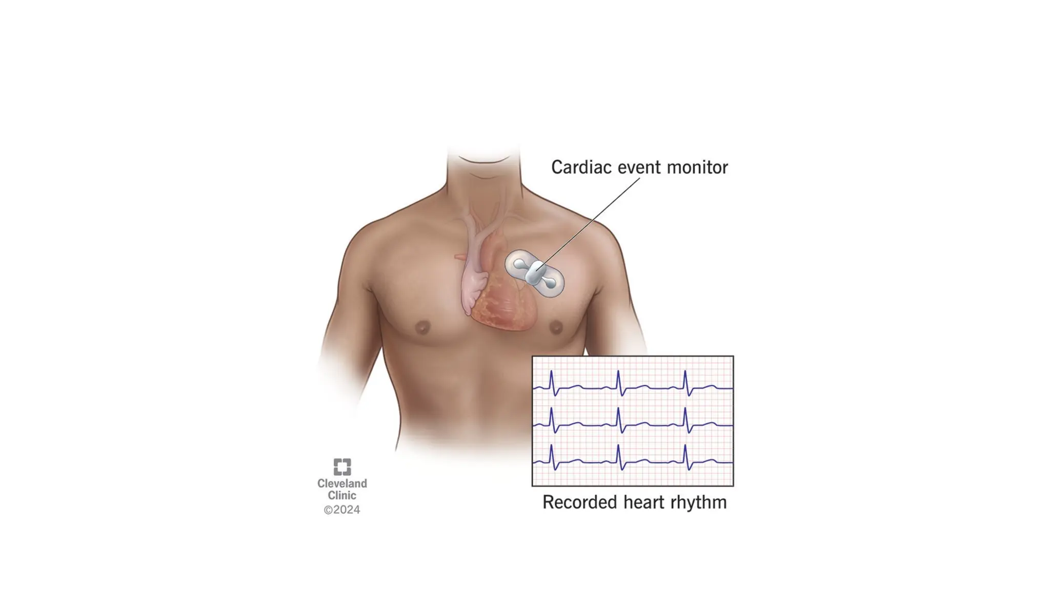
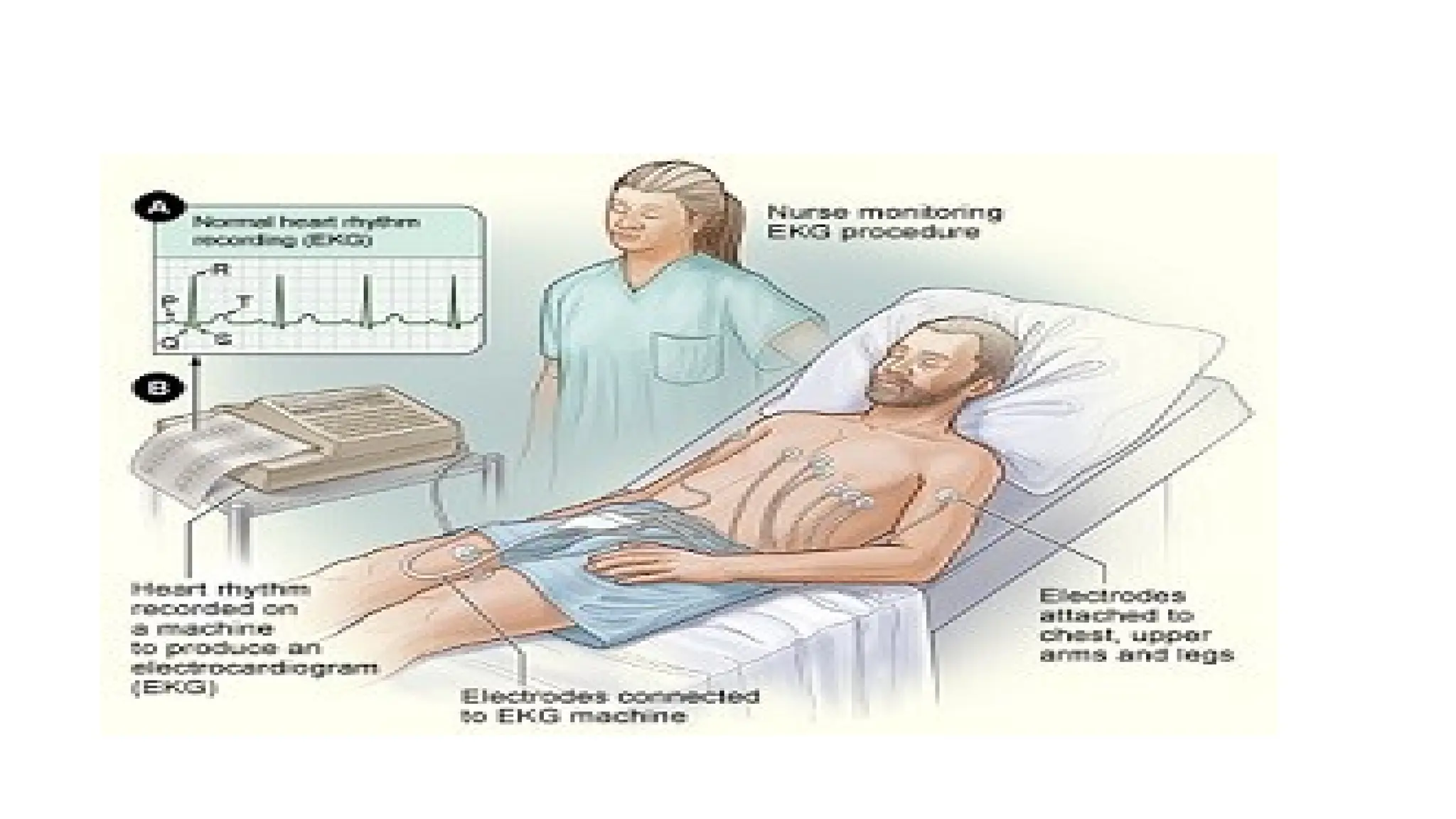
Heart monitor
• Aheart monitor is a small device you wear or carry that records your
heart rate and rhythm for your provider to review.
• Heart monitor devices can collect the same information as an
electrocardiogram (EKG), but they’re smaller than a deck of playing
cards.
• As you can have this battery-powered device with you for up to a
month, it’s good for recording abnormal heart rhythms (arrhythmias)
that don’t happen every day.
How Cardiac MonitoringWorks
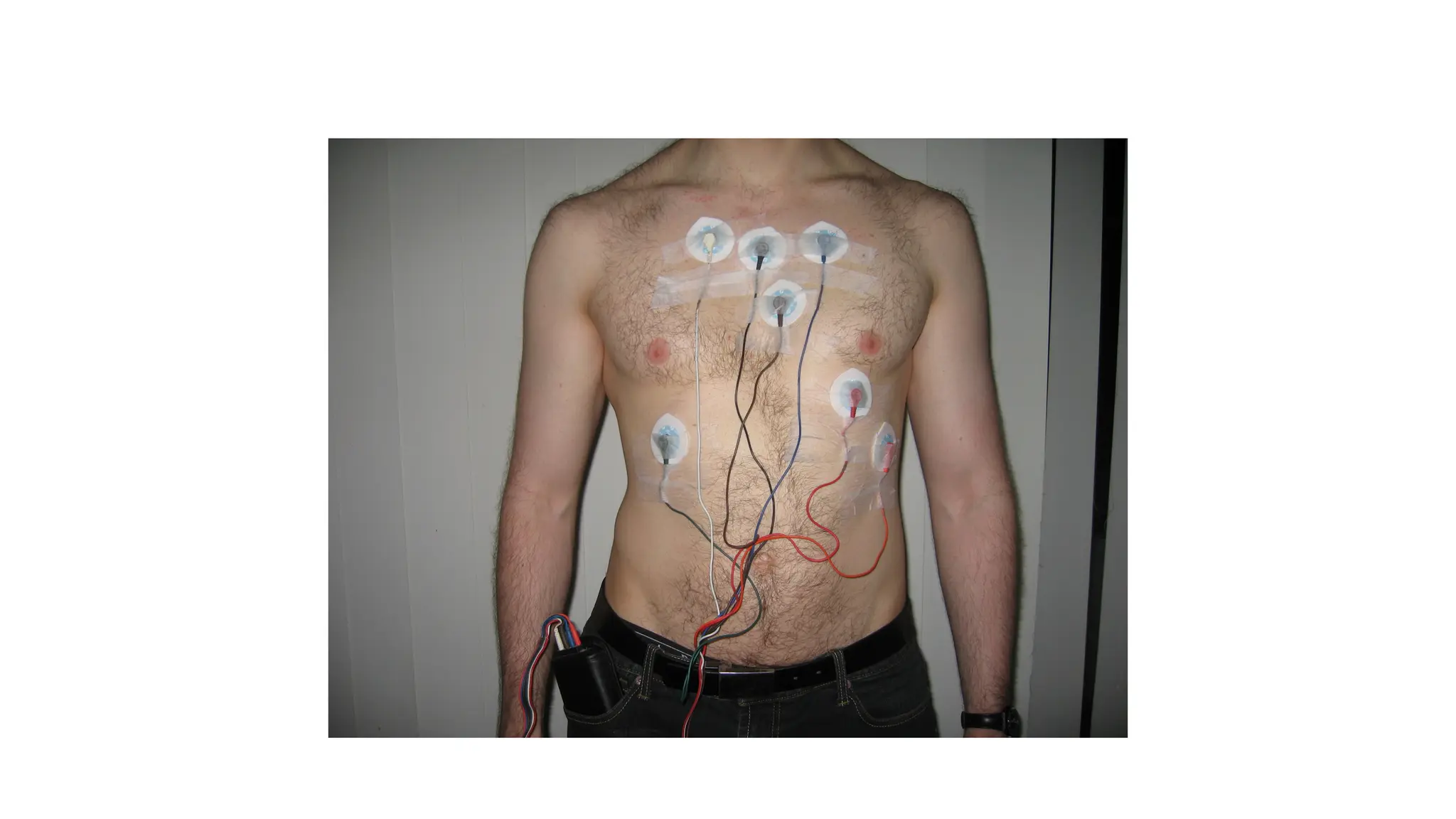
1.Electrodes:
Small, sticky patches called electrodes are placed on the skin of the chest to detect the heart's electrical activity.
2.Data Transmission:
Wires or wireless technology send the electrical signals to a small monitor box or a larger screen.
3.Monitoring:
A nurse or other healthcare provider can view these readings 24/7 on a special screen at a central nurses' station in a hospital setting.
4.Event Triggering:
In some devices, like an event monitor, a patient presses a button to save the ECG data when symptoms occur, capturing the electrical activity
before, during, and after the event.
15.
Purpose of CardiacMonitor Notes
• Detecting Abnormal Rhythms: The main purpose is to identify dangerous or
abnormal heart rhythms (arrhythmias) that might require medical intervention.
• Monitoring Patient Status: Notes provide crucial information about a patient's
cardiac status, helping healthcare providers choose the right treatment.
• Identifying Ischemia: Cardiac monitoring can help detect signs of ischemia (lack
of blood flow) or a heart attack.
• Assessing Impending Decompensation: The information gathered can signal
impending heart failure or other severe cardiac issues.
16.
Central monitor
• Acentral monitoring system (CMS) is a centralized hub that monitors
and manages multiple devices or systems, such as security cameras,
alarms, or patient vital signs, from a single location.
• It allows for real-time surveillance, data collection, and immediate
alerts, enabling proactive decisions and response from a central
control point, like in hospitals or for business security.
• In some government contexts, like in India, a CMS refers specifically
to a system for automated lawful interception and monitoring of
telecommunications.
17.
• These systemsintegrate data from various wired, wireless, and telemetry devices to monitor vital
signs like heart rate, blood pressure, and oxygen saturation.
• Key benefits include enabling remote monitoring, improving response times, reducing alarm fatigue,
and streamlining workflows by integrating with electronic health records (EHR).
• Data Collection:
Sensors and monitoring devices (like ECG, pulse oximeters, and blood pressure cuffs) attached to
patients continuously collect physiological data.
• Centralized Display:
This data is transmitted to a central station, where it can be viewed alongside information from other
patients on a single interface.
• Remote Access:
Authorized healthcare professionals can access patient data from various locations, including through
mobile devices, both inside and outside the hospital.
• Integration:
CMS can connect with other hospital systems, such as Electronic Health Records (EHR), to streamline
documentation and provide a comprehensive patient history.
18.
• CMS technologyis crucial in high-acuity settings like intensive care units (ICUs)
and emergency rooms, but its benefits extend throughout a hospital and even into
remote care settings.
• Improved patient safety: Continuous, automated monitoring provides early
warnings of patient deterioration, allowing for timely intervention and preventing
adverse events.
• Reduced alarm fatigue: Advanced CMS features include intelligent alarm
management tools that filter and prioritize alarms based on clinical context. This
reduces unnecessary noise and allows staff to focus on critical issues.
• Enhanced staff efficiency: One technician can remotely monitor a large number
of patients, freeing up on-site clinical staff for direct patient care.
• Streamlined workflow: Integration with EMRs and other hospital information
systems automates data entry and improves access to patient information,
reducing the administrative burden on clinicians.
19.
• Support forremote care: Telemonitoring capabilities enable
healthcare providers to monitor patients remotely, which is particularly
useful for managing chronic diseases or for patients recovering at
home.
• Data-driven decision making: The stored patient data and integrated
analytics help clinicians analyze trends and inform treatment plans.
Some systems use AI to offer predictive insights.
20.
• The coreCMS model can be adapted for different needs and clinical settings.
• Wireless CMS: Supports mobile patients via wireless or telemetry transmitters,
allowing for continuous monitoring as they move around.
• Wired CMS: Connects bedside monitors directly to the central station, often used
in ICUs where patients are stationary.
• Remote patient monitoring (RPM): Used for managing patients outside the
hospital, such as those with chronic illnesses being monitored from home.
• Multi-room or multi-unit CMS: Monitors critical conditions across different
rooms or units from a single control center. This is often used for managing
environmental factors like temperature and pressure in critical areas.
• ICU-specific CMS: Tailored for intensive care, these systems often integrate with
specialized devices like ventilators and infusion pumps for a unified view.
Types of central monitoring systems
21.
Measurement of HeartRate
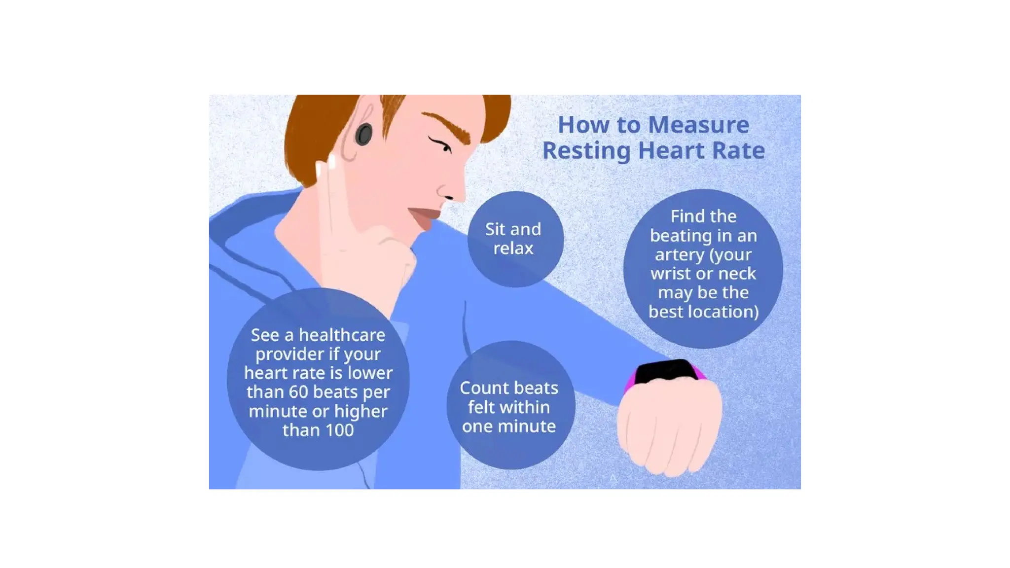
•You can measure your heart rate manually by checking your pulse at the wrist or
neck, or with a heart rate monitor or smartwatch.
• A resting heart rate for adults is typically between 60 and 100 beats per minute (bpm)
• How to measure your pulse manually
• To get the most accurate reading, relax for 5 to 10 minutes before you begin.
• At the wrist
• Turn one arm so your palm faces up.
• Place the index and middle fingers of your other hand on the inside of the wrist, just
below the base of the thumb.
• Press firmly but gently until you feel a throbbing sensation. Do not use your thumb,
as it has its own pulse.
• Count the beats for 30 seconds and multiply by two to get your heart rate in beats per
minute (bpm). Alternatively, count for a full 60 seconds.
22.
• At theneck
• Place your index and middle fingers on one side of your neck, just
below your jawline and next to your windpipe.
• Press gently until you feel a pulse.
• Count the beats for 30 seconds and multiply by two for your heart
rate in bpm.
• Caution: Do not press on the arteries on both sides of the neck at the
same time, as this can slow blood flow to the brain and cause
dizziness.
23.
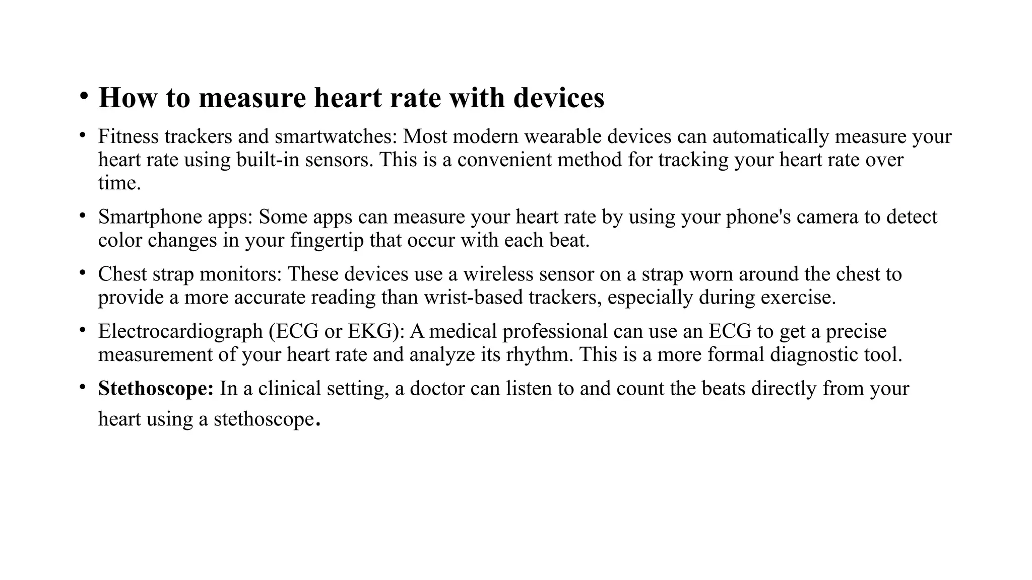
• How tomeasure heart rate with devices
• Fitness trackers and smartwatches: Most modern wearable devices can automatically measure your
heart rate using built-in sensors. This is a convenient method for tracking your heart rate over
time.
• Smartphone apps: Some apps can measure your heart rate by using your phone's camera to detect
color changes in your fingertip that occur with each beat.
• Chest strap monitors: These devices use a wireless sensor on a strap worn around the chest to
provide a more accurate reading than wrist-based trackers, especially during exercise.
• Electrocardiograph (ECG or EKG): A medical professional can use an ECG to get a precise
measurement of your heart rate and analyze its rhythm. This is a more formal diagnostic tool.
• Stethoscope: In a clinical setting, a doctor can listen to and count the beats directly from your
heart using a stethoscope.
24.
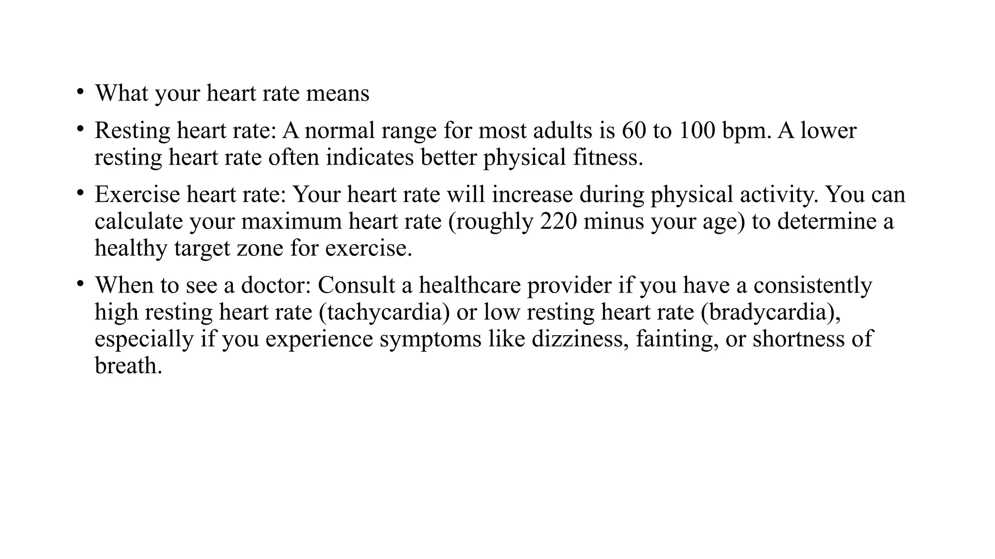
• What yourheart rate means
• Resting heart rate: A normal range for most adults is 60 to 100 bpm. A lower
resting heart rate often indicates better physical fitness.
• Exercise heart rate: Your heart rate will increase during physical activity. You can
calculate your maximum heart rate (roughly 220 minus your age) to determine a
healthy target zone for exercise.
• When to see a doctor: Consult a healthcare provider if you have a consistently
high resting heart rate (tachycardia) or low resting heart rate (bradycardia),
especially if you experience symptoms like dizziness, fainting, or shortness of
breath.
26.
Measurement of pulseRate
• When heart muscle contracts , blood is ejected from the ventricles and
a pulse of pressure is transmitted through the circulatory system.
• This pulse can be measured at various points.
• We can sense the pulse by placing our finger tip over the radial artery
in the wrist.
• This pulse travels at the speed of 5 to 15m per second.
• Photoelectric method is commonly employed to measure the pulse.
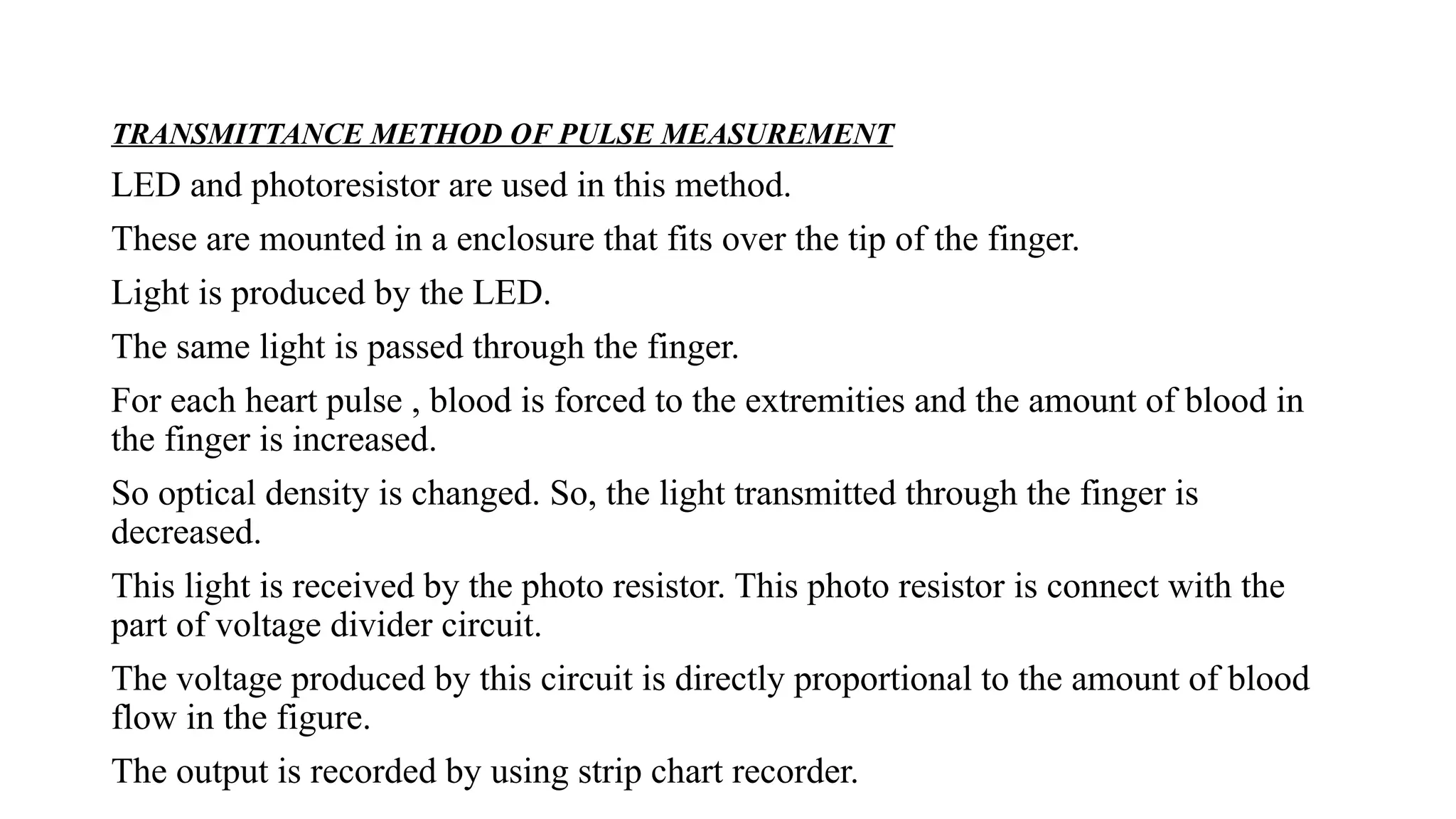
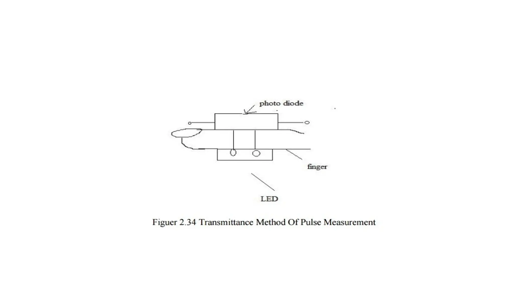
TRANSMITTANCE METHOD OFPULSE MEASUREMENT
LED and photoresistor are used in this method.
These are mounted in a enclosure that fits over the tip of the finger.
Light is produced by the LED.
The same light is passed through the finger.
For each heart pulse , blood is forced to the extremities and the amount of blood in
the finger is increased.
So optical density is changed. So, the light transmitted through the finger is
decreased.
This light is received by the photo resistor. This photo resistor is connect with the
part of voltage divider circuit.
The voltage produced by this circuit is directly proportional to the amount of blood
flow in the figure.
The output is recorded by using strip chart recorder.
30.
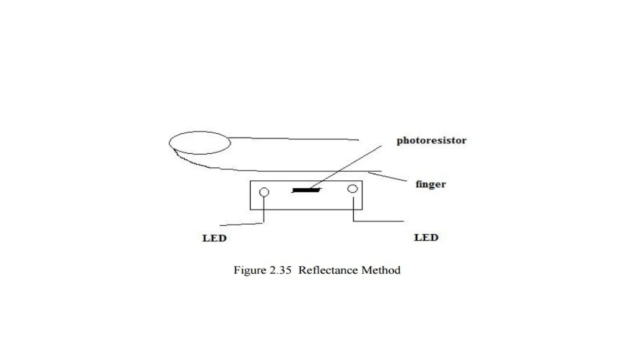
REFLECTANCE METHOD
• Inreflectance method, LED is placed adjacent to the photoresistor.
• LED emits the light.
• This light is reflected form the skin and the tissues falls on the photo resistor.
• The reflected light varies depending upon the blood flow in the finger.
• The photo resistor is connected as a part of the voltage divider circuit.
• The output obtained is directly proportional to the amount of blood in the finger.
The output can be recorder using strip chart recorder.
32.
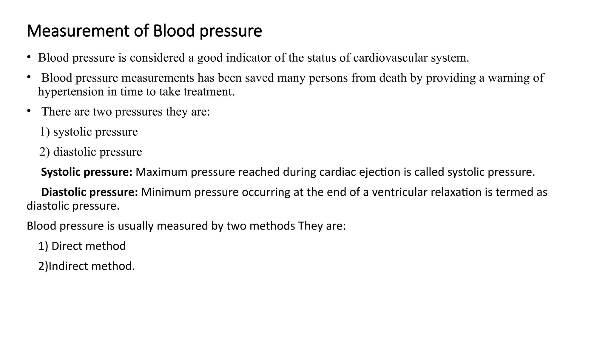
Measurement of Bloodpressure
• Blood pressure is considered a good indicator of the status of cardiovascular system.
• Blood pressure measurements has been saved many persons from death by providing a warning of
hypertension in time to take treatment.
• There are two pressures they are:
1) systolic pressure
2) diastolic pressure
Systolic pressure: Maximum pressure reached during cardiac ejection is called systolic pressure.
Diastolic pressure: Minimum pressure occurring at the end of a ventricular relaxation is termed as
diastolic pressure.
Blood pressure is usually measured by two methods They are:
1) Direct method
2)Indirect method.
33.
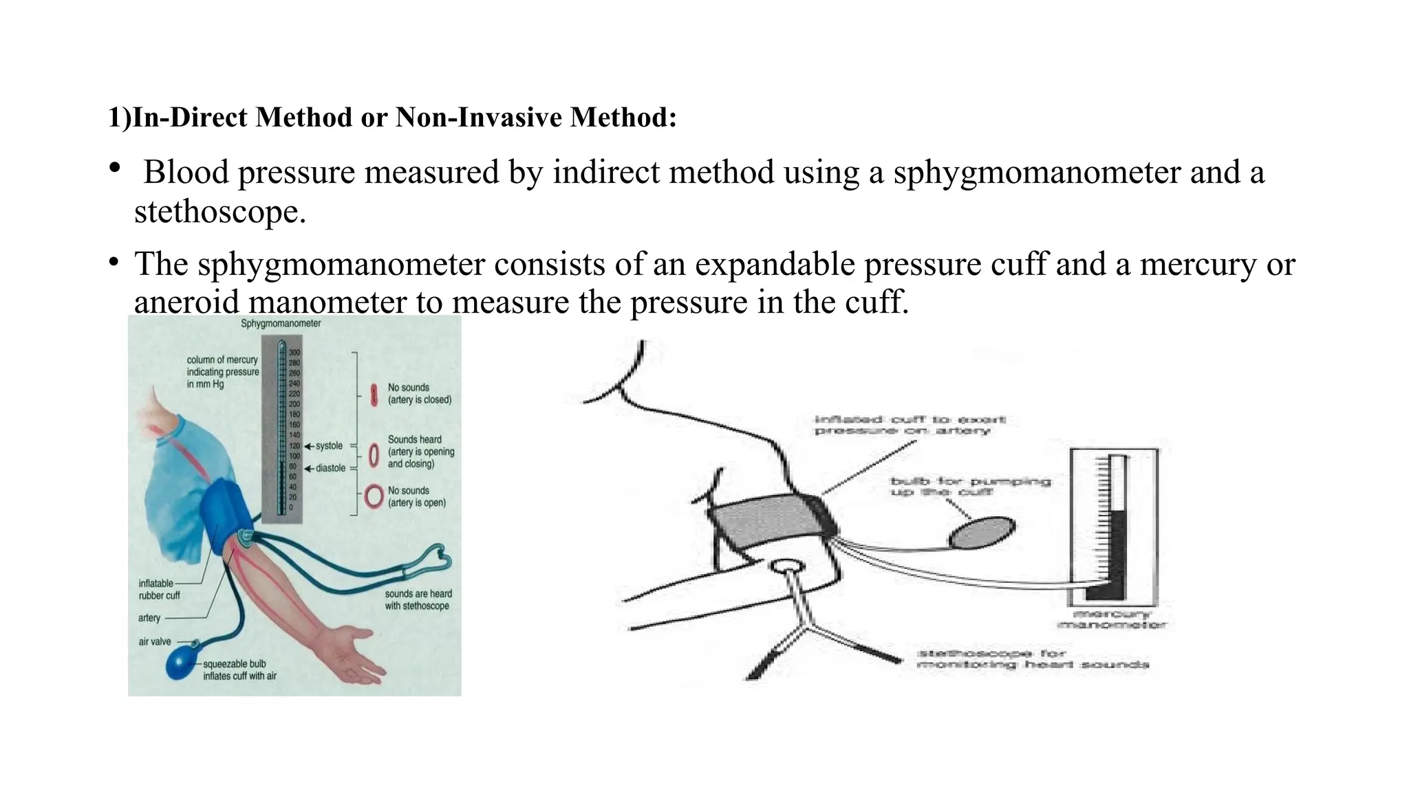
1)In-Direct Method orNon-Invasive Method:
• Blood pressure measured by indirect method using a sphygmomanometer and a
stethoscope.
• The sphygmomanometer consists of an expandable pressure cuff and a mercury or
aneroid manometer to measure the pressure in the cuff.
34.
Principle:
• When thecuff is placed on the upper arm and expanded arterial blood can flow but only when
the arterial pressure exceeds the pressure in the cuff.
• The sounds generated by this disturbance can be heard through a stethoscope placed over the
downstream of artery from the cuff. Then the sound is known as Korotkoff sounds.
• If the pressure exceeds above systolic pressure no sound can be heard through the stethoscope.
• If the pressure gradually reduced as soon as cuff pressure falls below systolic pressure, a small
amount of blood rush the cuff and Korotkoff sounds being too heard through stethoscope.
• The pressure in the cuff continues to drop and block the vessel during any part of the cycle
then Korotkoff sound disappears, and the value is recorded as diastolic pressure. It is usually 80
mmHg.
• Familiar method of locating the systolic and diastolic pressure values by listening the
Korotkoff sounds is called Auscultatory method of sphygmomanometry.
• An alternative method that the physician can identifies the blood flow and feeling the pulse is
called palpatory method.
35.
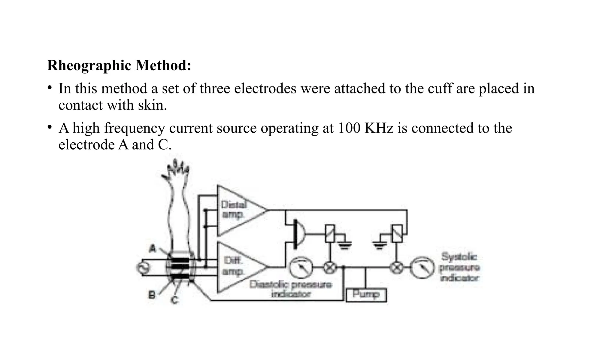
Rheographic Method:
• Inthis method a set of three electrodes were attached to the cuff are placed in
contact with skin.
• A high frequency current source operating at 100 KHz is connected to the
electrode A and C.
36.
• The impedancebetween any two electrodes is pressure before pressurizing the
cuffs and modulated in accordance with blood flow pulsations in the artery.
• Therefore, arterial pulses can be detected by the demodulation and amplification
of this modulation.
• The same principle what we have seen in before takes place here too the only
difference is diastolic pressure and systolic pressure are shown by the indicators.
37.
2) Direct Methodor Invasive Method:
A direct method of pressure measurement is used when the highest degree of
absolute accuracy, dynamic response and continuous monitoring is required.
This method is also used to measure the pressure in deep regions inaccessible
by indirect mean.
Direct measurement of blood pressure is usually obtained by any one of the
three methods.
• Percutaneous insertion
• Catheterization
• Implantation of a transducer in a vessel or in the heart
Catheter tip probe: In this type, the sensor is mounted on the tip of the probe
and pressure applied on it are converted to the proportional electrical signal.
38.
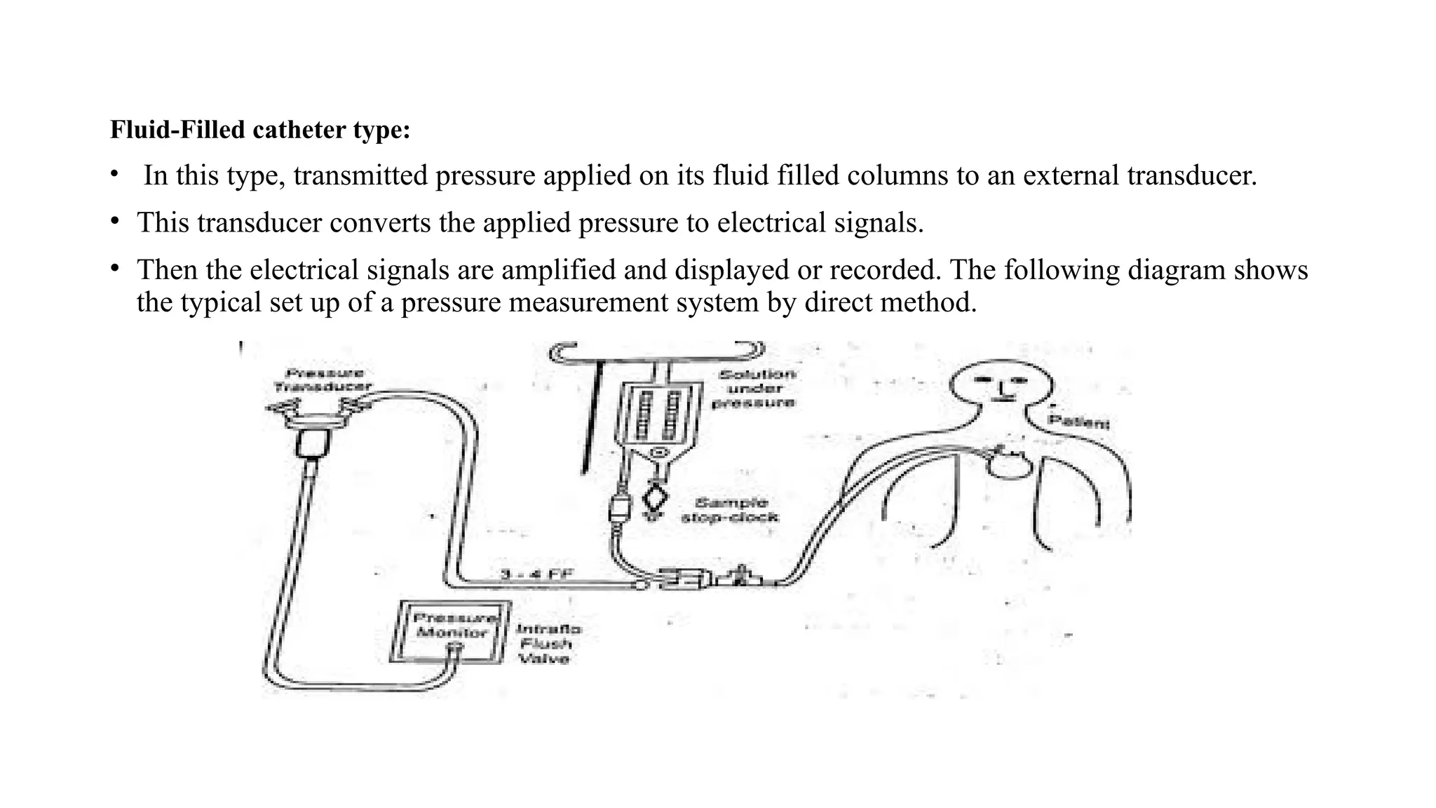
Fluid-Filled catheter type:
•In this type, transmitted pressure applied on its fluid filled columns to an external transducer.
• This transducer converts the applied pressure to electrical signals.
• Then the electrical signals are amplified and displayed or recorded. The following diagram shows
the typical set up of a pressure measurement system by direct method.
39.
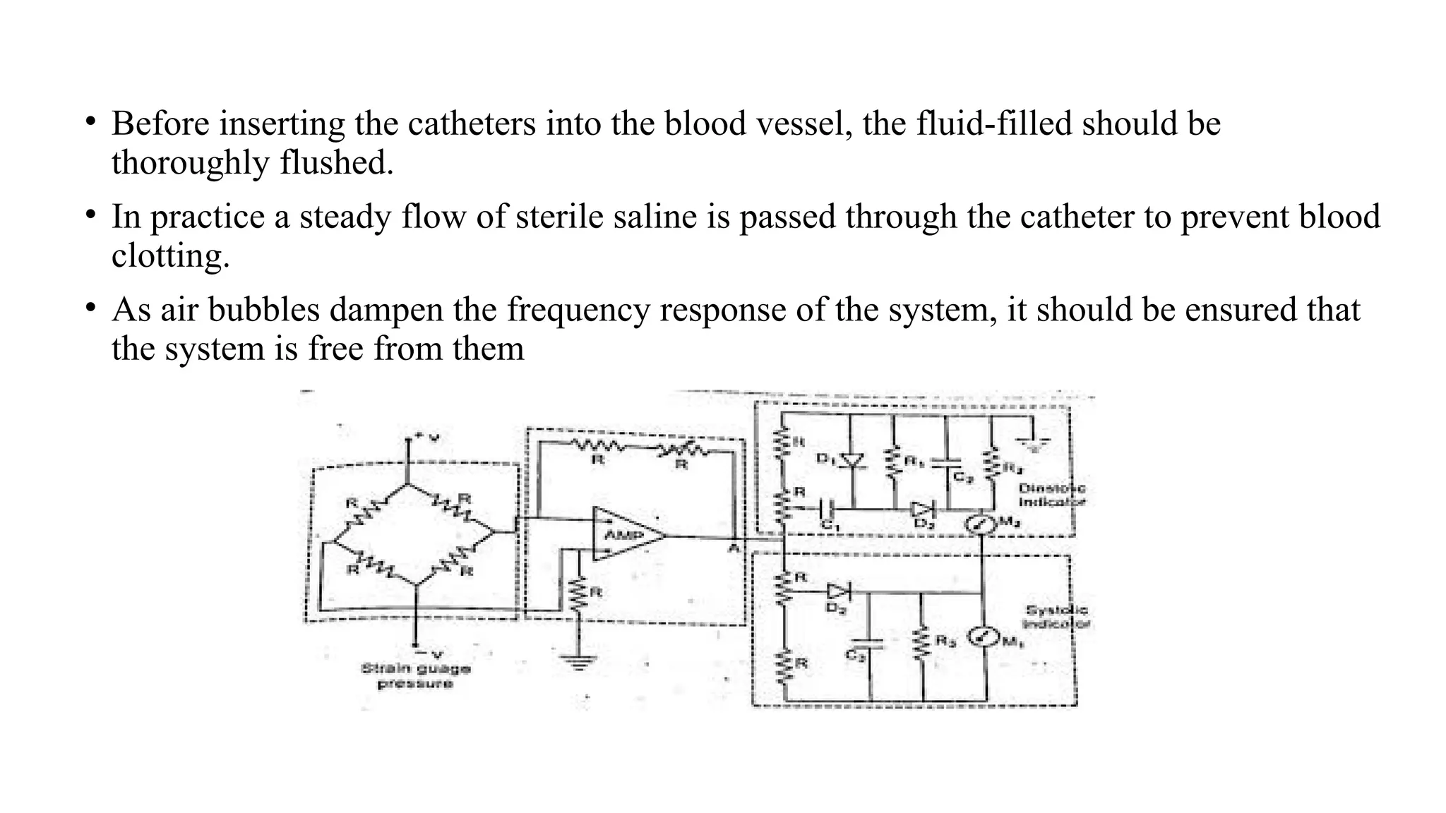
• Before insertingthe catheters into the blood vessel, the fluid-filled should be
thoroughly flushed.
• In practice a steady flow of sterile saline is passed through the catheter to prevent blood
clotting.
• As air bubbles dampen the frequency response of the system, it should be ensured that
the system is free from them
40.
• A simplifiedcircuit diagram commonly used for processing electrical signals
received from the pressure transducers for measurements of arterial pressure.
Working:
• The transducer is excited with a 5V DC excitation.
• The electrical signals corresponding to the arterial pressure are amplified in an
operational amplifier or a carrier amplifier.
• Modern preamplifier for processing pressure signal is the isolated type.
• The input stage is a differential circuit, which amplifies pressure change and it
sensed from the patient connected circuit.
• Gain of the amplifier can be adjusted depending upon the sensitivity of the
transducer.
• There are two types of meters with indicator available to measure diastolic
pressure and systolic pressure.
41.
Case i:
• Forthe measurement of systolic pressure, a conventional peak reading type voltmeter is
used.
• When a positive pulse from amplifier is separated at A, diode D3 conducts and the
capacitor C3 is charging upto peak value of input signal, corresponding to systolic value.
• Capacitor C3 and Resistor R3 is used to set time constant RC to get steady state output
in the indicating meter.
Case ii:
• Diastolic pressure value is derived in an indirect way.
• A clamping circuit consisting of C1 and D1 is used to develop a voltage equal to peakto-
peak value of the pulse pressure.
• The voltage appears across R1 then diode D2 conducts and capacitor charges to peak
value of the pulse signal.
• Then the diastolic pressure is indicated by a second meter M2.
It shows the difference between peak systolic and peak-to-peak pulse pressure signal.
42.
TEMPERATURE MEASUREMENT:
• Temperatureis one of the inductor of the general well being. Two types of temperature
measurements can be obtained from the body. These are
1)Systematic temperature
2)Surface temperature
Systematic temperature is the temperature of the internal region of the body.
Usually, the heat is generated by the active tissues of the body and heat is lost by the body to the
environment.
But, the temperature of the body is maintained carefully.
The normal mouth temperature is 370
C. the normal underarm temperature is about 10
C lower than
the above temperature. Systemic temperature is measured accurately at tympanic membrane of ear.
The brain contains the temperature control centre for the body.
43.
Systemic body temperaturemeasurement
Mercury thermometer is used to measure the systemic temperature.
It is inexpensive to use..
when continuous temperature recording is necessary, then, thermocouple or thermistor can be used.
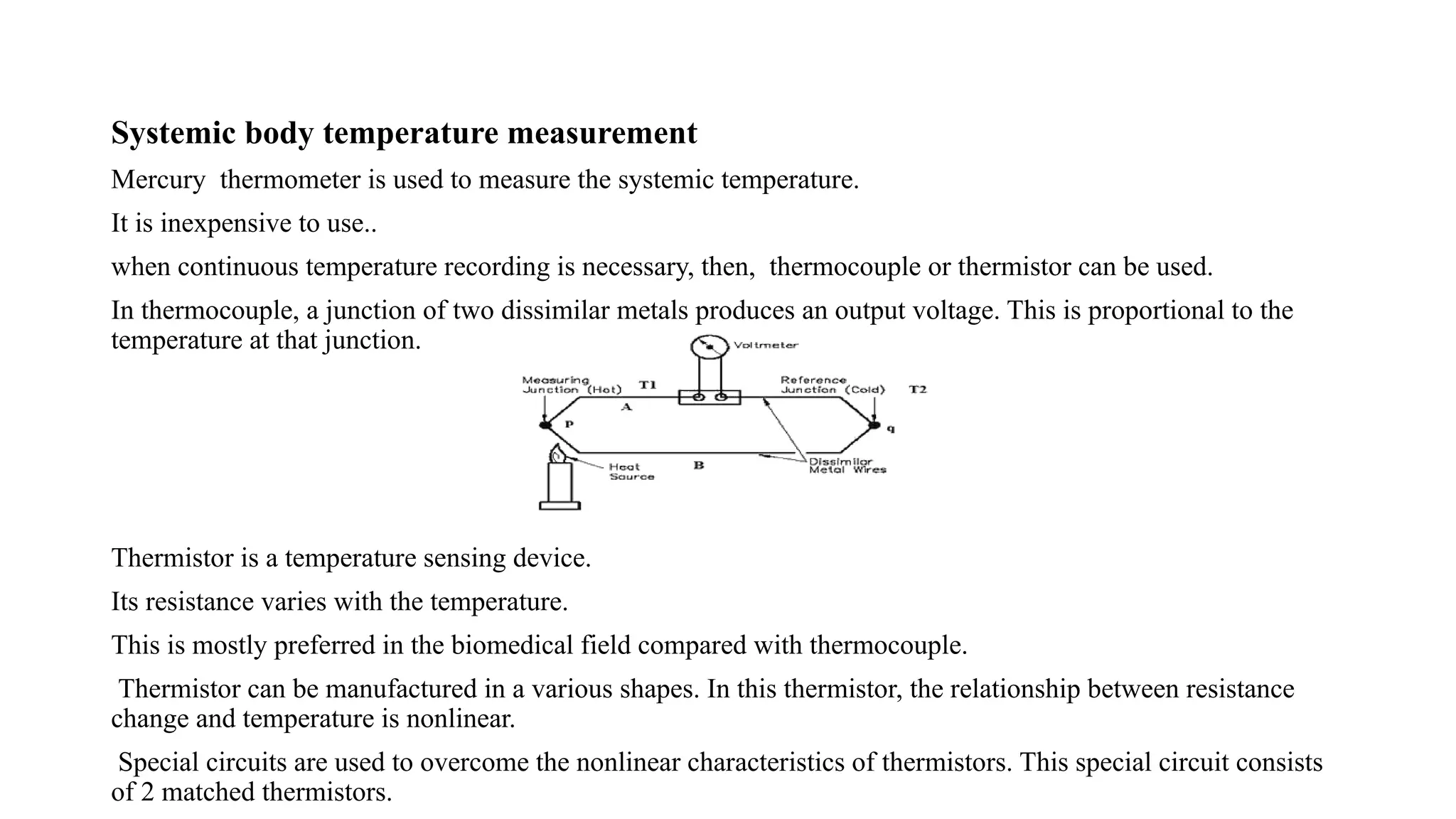
In thermocouple, a junction of two dissimilar metals produces an output voltage. This is proportional to the
temperature at that junction.
Thermistor is a temperature sensing device.
Its resistance varies with the temperature.
This is mostly preferred in the biomedical field compared with thermocouple.
Thermistor can be manufactured in a various shapes. In this thermistor, the relationship between resistance
change and temperature is nonlinear.
Special circuits are used to overcome the nonlinear characteristics of thermistors. This special circuit consists
of 2 matched thermistors.
44.
Problems associated withthermistor
Self heating is very important problem in thermistor. This problem can be overcome by limiting the current
used in measurement. The power dissipation of thermistor is to be maintained in milliwatts range to
overcome this problem
Thermistor probe should be chosen correctly based on
1)Resistance range
2) Sensitivity
Skin temperature measurement:
Skin temperature is not constant throughout the body. It is varied from 300C to 350C. Various factors affect
the skin temperature are given below
· How fat covers over capillary area
· How the skin portion is exposed to ambient temperature
· Blood circulation pattern beneath the skin
Probe used for measurement
A small flat thermistor probe is used to measure the skin temperature.
45.
Infrared thermometer
• Itis a device used to measure skin surface temperature. It is used to locate breast
cancer. It is also used to identify the spots in which blood circulation is poor.
46.
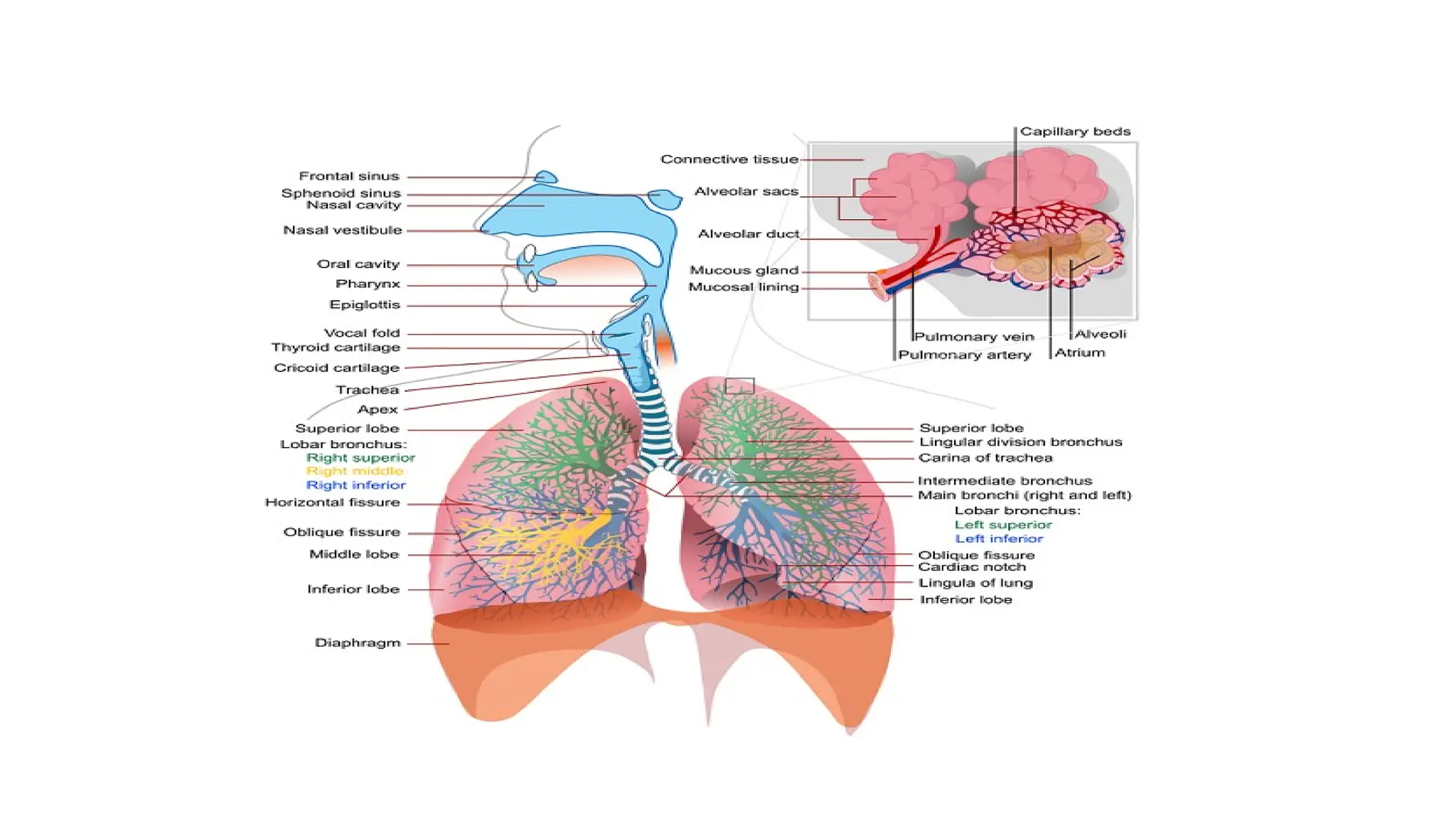
Measurement of RespiratorySystem
• Respiratory system provides a means of acquiring oxygen and eliminating CO2. Various laws are involved
in the understanding of respiratory functions.
• Various Gas laws are given below:
1) BOYLE’S LAW: It states that at constant temperature, the volume of gas varies inversely with the
pressure.
V2/V1 =P1/P2 here temperature T= constant
• V2= Final volume
• V1 = Initial volume
• P1 = Original (initial) pressure
• P2 = Final pressure
47.
2.CHARLE’S LAW: Itstates that, at constant pressure, the volume of gas is directly proportional to
the absolute temperature.
V2/V1 =T2/T1 Here pressure P=constant
• V2, V1 =Final, initial volume
• T1 =original temperature
• T2 = Final temperature
3 . HENRY’S LAW : It states that, if the temperature is constant, the quantity of a gas that goes into
a solution is directly proportional to the partial pressure of that gas . The gas with the greater partial
pressure will have more mass in solution.
48.
4. DALTON’S LAW: It states that, the total pressure exerted by a mixture of
gases is equal to the sum of the partial pressures of various gases.
PT =P1 + P2 + …………… +Pn
PT = total pressure
P1, P2 ,P3 = partial pressure of various gases
49.
• TYPES OFRESPIRATION
1)Internal Respiration
2)External Respiration
Respiration is nothing but the interchange of gases between an
organism and the living medium
Internal respiration is the exchange of gases between the blood stream
and nearby cells
External respiration is the exchange of gases between the lungs and
blood stream .
52.
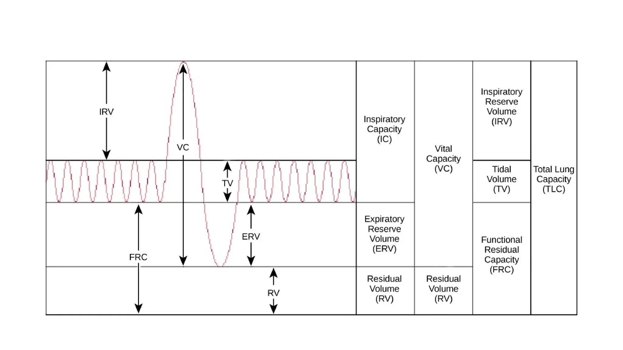
• Lungs Volumesand Capacities (Respiration Parameters) Or (LVC)
Respiration parameters are used to indicate the state of respiratory function ,
including lung volumes and capacities , airway resistance , lung compliance , etc .
• Dead Air
Only a portion of the air entering the respiratory system actually reaches the
alveoli . The volume of air that is not available for gas exchange with the blood is
known as dead air . The total dead space is less less than 30 percentage of the total
volume .
53.
Tidal Volume (TV)
•Tidal volume is the depth of breathing or the volume of gas inspired
or expired during each respiratory cycle. It is equal to 500 ml for a
normal person .
Inspiratory Reserve Volume (IRV)
• It is the maximal amount of gas that can be inspired from the end-
inspiratory position ( Extra inspiration from the high peak tidal volume
. It is equal to 3600 ml for a normal person
54.
Expiratory reserve volume(ERV)
• It is the maximal amount of gas that can be end expiratory level. It is equal to 1200 ml.
Residual Volume(RV)
• It is the amount of gas remaining in the lungs at the end of maximal expiration. It is
equal to 1200 ml.
Minute Volume (MV)
• It is the volume of air breathed normally for 1 minute.
55.
Total Lung Capacity(TLC)
•It is the amount of gas contained in the lungs at the end of maximal
inspiration and it is the sum of inspiratory capacity(IC) and functional
residual capacity (FRC). TLC is of 6000 ml for a normal person.
Vital Capacity(VC)
• It is the maximum amount of gas that can be expelled from the lungs
by forceful effort from maximal inspiration. It is 4800 ml for a normal
person.
56.
Inspiratory Capacity(IC)
• Itis the maximum amount of gas that can be inspired from the resting
expiratory level and it is the sum of tidal volume and inspiratory
reserve volume. It is equal to 3600 ml for a normal person.
Functional Residual Capacity(FRC)
• It is the amount of gas remaining in the lungs at the resting expiratory
level. FRC = ERV + RV
57.
Airway resistance
• Itrelates to the ease with air flows through tubular respiratory structures. In smaller tubes,
airway resistance is high.
Lung Compliance
• It is the ability of the alveoli and lung tissue to expand on inspiration.
Lung Elasticity
• It is the ability of the lung’s elastic tissues to recoil during expiration
Intra thoractic Pressure
• It is the positive and negative pressure occur within the thoracic cavity
58.
• It isthe positive and negative pressure occur within the thoracic cavity Types of
respiration rate measurement
• 1. Displacement method
• 2. Thermistor method
• 3. Impedance pneumography
• 4. CO2 method
• 5. Apnoea detectors
59.
1) Displacement method:
Inthis method the transducer is hold by an elastic band which goes around the chest.The respiratory movements
results in a corresponding resistance changes of the strain gauge. It is connected as one arm of a wheatstone bridge
circuit. Its output varies with chest expansion. This output corresponds to the respiration activity.
2) Thermistor Method
Generally there is a temperature difference between inspired and expired air. This temperature is sensed by placing
thermistor in front of nostrils. Thermistor is placed by using suitable stand. The thermistor is connected with the
bridge circuit. So unbalance signal is amplified to get the respiratory activity.
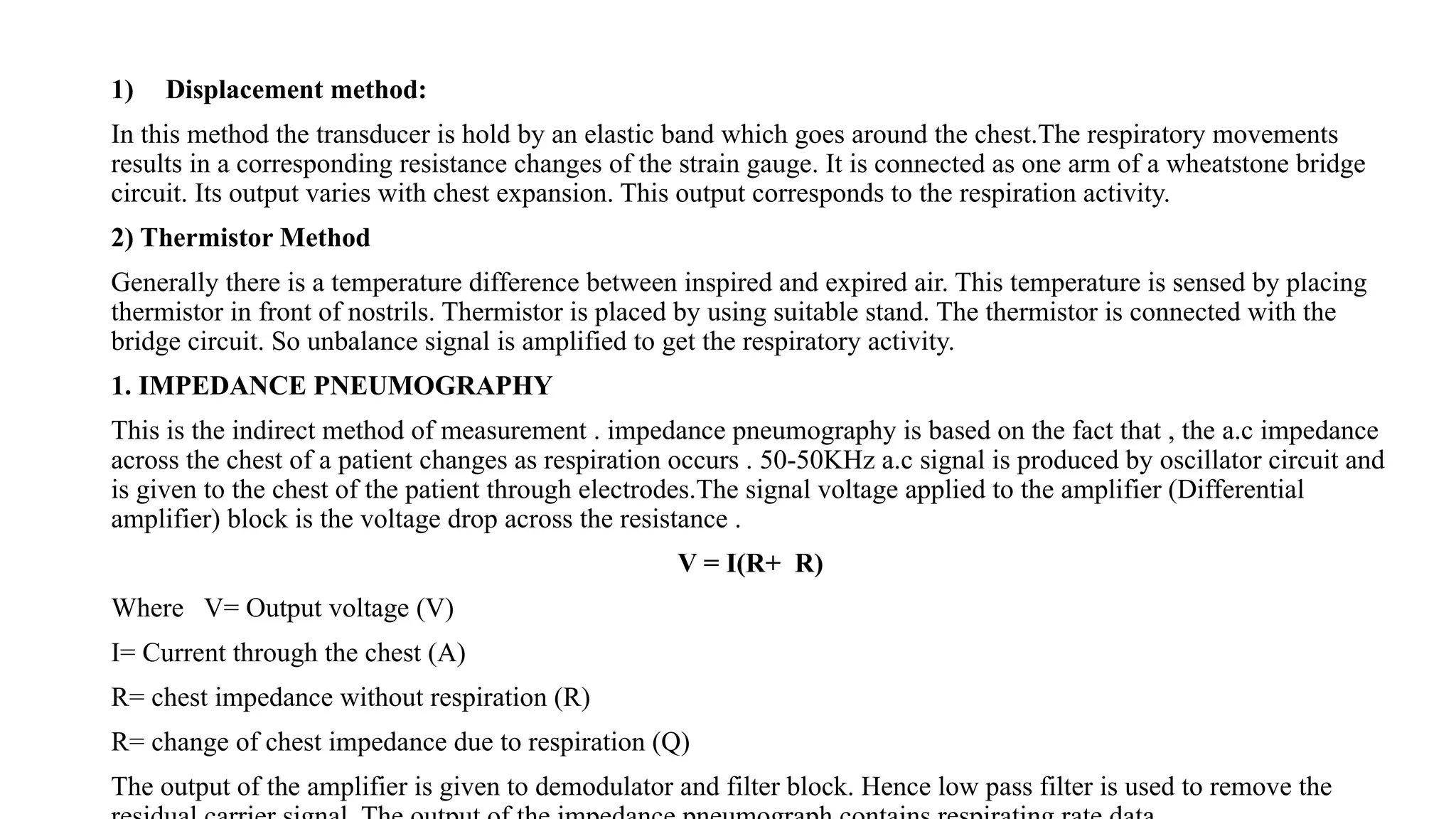
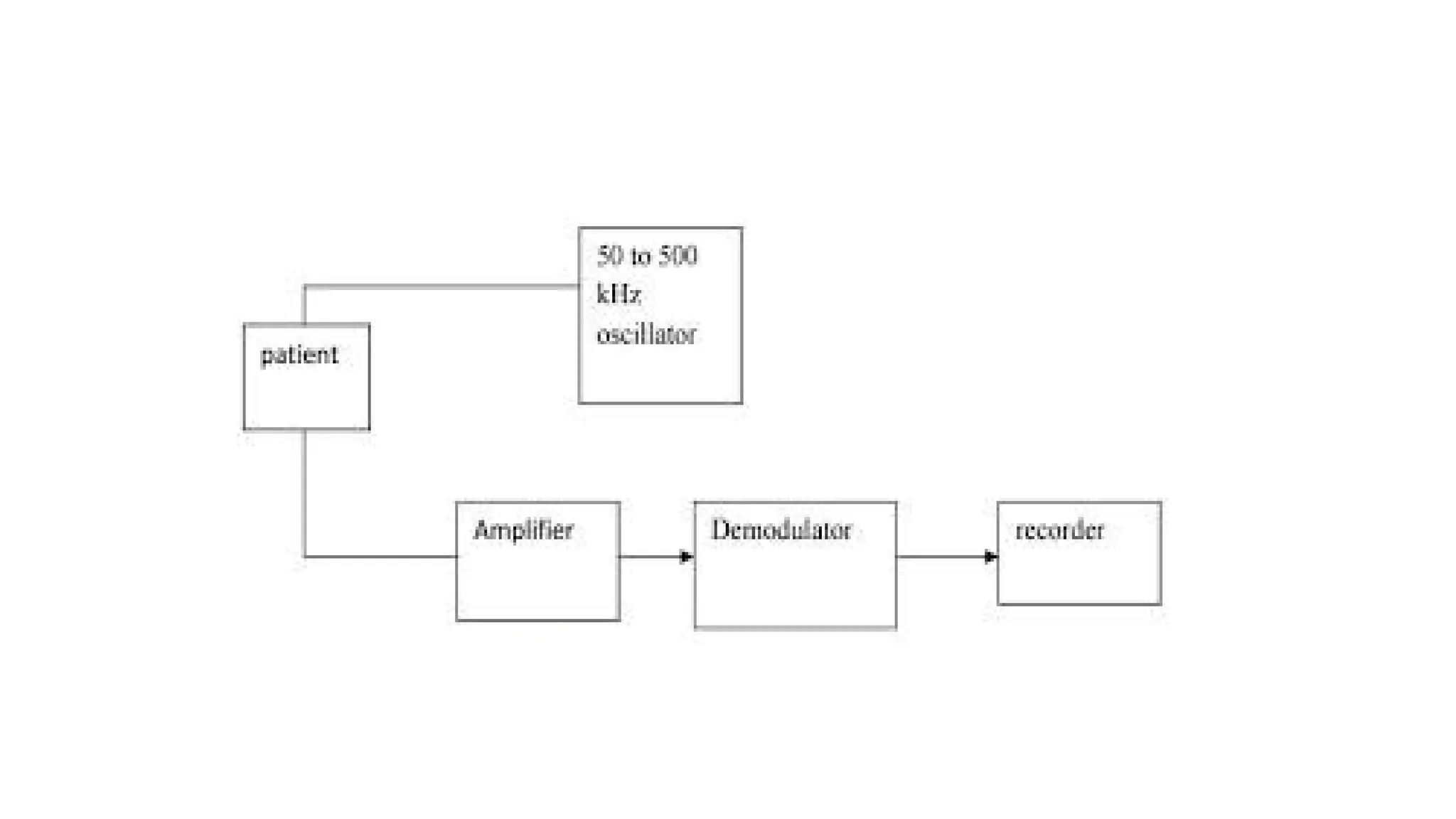
1. IMPEDANCE PNEUMOGRAPHY
This is the indirect method of measurement . impedance pneumography is based on the fact that , the a.c impedance
across the chest of a patient changes as respiration occurs . 50-50KHz a.c signal is produced by oscillator circuit and
is given to the chest of the patient through electrodes.The signal voltage applied to the amplifier (Differential
amplifier) block is the voltage drop across the resistance .
V = I(R+ R)
Where V= Output voltage (V)
I= Current through the chest (A)
R= chest impedance without respiration (R)
R= change of chest impedance due to respiration (Q)
The output of the amplifier is given to demodulator and filter block. Hence low pass filter is used to remove the
61.
2) CO2 Method
•Respiration rate can be measured by measuring CO2 in expired air.
• This CO2 method of measurement is based on the absorption property of infrared rays by certain gases .
• When infrared rays are passed through the expired air which contains certain amount of CO2, some of
radiations are absorbed by it.
• So, there is loss of heat energy associated with the rays .The detector changes the loss in heating effect of the
rays into an electrical signal. It is used to get the average respiration rate.
• Two infrared sources are available in this set up. The beam from one infrared source falls on the test cuvette
side. The beam from another infrared source falls on the reference cuvette side
• The detector has two identical portions.
• These portions are separated by a thin, flexible metal diaphragm.
• The detector is filled with a sample of pure CO2. Because of the absorption of CO2 in the test cuvette.
• The beam falling on the test side of the detector is weaker that falling on the reference side. The gas in
reference side is heated more than that on the test side.
• So diaphragm is pushed slightly to the test side of the detector.
• This diaphragm forms one plate f a capacitor. The a.c signal appears across the detector is amplified and
recorded using recorder. The amplified output is integrated. It is used for continuous monitoring the respiration
rate.
63.
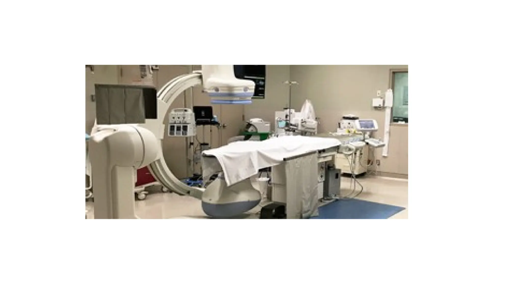
Catheterization laboratory instrumentation
•Catheterization laboratory instrumentation in healthcare involves advanced electronic systems for
diagnosis, monitoring, and intervention during cardiac procedures. The setup includes specialized
imaging, monitoring, and interventional devices that are integral to patient care and procedural
success.
Core Electronic Instruments
• Imaging Systems: Most cath labs use digital fluoroscopy and angiography systems with flat panel
detectors for real-time visualization of the heart and arteries. Biplane systems provide enhanced
imaging from two X-ray sources.
• Hemodynamic Monitoring: Devices monitor blood pressure, oxygen saturation, and detailed
circulatory parameters, offering continuous data for immediate clinical decisions.
• Electrophysiology Equipment: Includes 3D mapping systems, ablation catheters, pacemakers, and
defibrillators for identifying and treating arrhythmias through electrical activity monitoring and
intervention.
• Patient Monitoring: ECG, heart rate, and oxygen saturation monitors provide feedback throughout
the procedure and alert clinicians to complications.
• Recording Systems: Digital recording and viewing equipment archive live X-ray images and
procedural data for review and documentation.
65.
Safety and SupportElectronics
• Radiation Safety: Lead aprons, shields, and real-time radiation dose monitors protect staff
and patients from exposure during imaging.
• Sterilization and Infection Control: Electronic controls manage scrub areas, sterile drapes,
and air handling systems to maintain aseptic conditions.
Team Roles in the Lab
• Interventional cardiologists operate the imaging and intervention systems.
• Cardiac physiologists set up hemodynamic monitoring and ECG equipment.
• Nurses and technologists assist in equipment operation, patient monitoring, and data
management.
Common Procedures Supported
• Angiograms, angioplasty, stenting, and pacemaker implantations using catheters and real-
time electronics.
• Detailed vessel imaging with intravascular ultrasound (IVUS) and contrast dye.
66.
• UNIT- IV:Biomedical Telemetry and Telemedicine: Wireless Telemetry, Single
Channel Telemetry Systems, Multi-channel Wireless Telemetry Systems, Multi-
patient Telemetry, Implantable Telemetry Systems, Transmission of Analog
Physiological Signals, Over Telephone, Telemedicine.
• UNIT- V: Therapeutic devices: Need for Cardiac Pacemaker, Implantable
Pacemakers, DC Defibrillator, Electronics in the Anaesthetic Machine.
67.
Biomedical Telemetry andTelemedicine
BIOTELEMETRY:
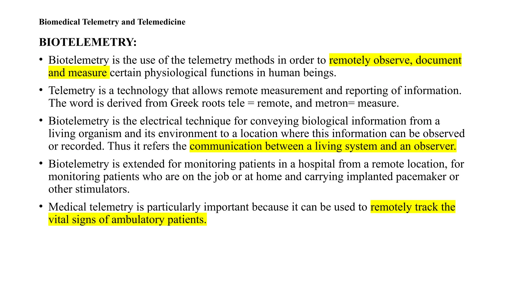
• Biotelemetry is the use of the telemetry methods in order to remotely observe, document
and measure certain physiological functions in human beings.
• Telemetry is a technology that allows remote measurement and reporting of information.
The word is derived from Greek roots tele = remote, and metron= measure.
• Biotelemetry is the electrical technique for conveying biological information from a
living organism and its environment to a location where this information can be observed
or recorded. Thus it refers the communication between a living system and an observer.
• Biotelemetry is extended for monitoring patients in a hospital from a remote location, for
monitoring patients who are on the job or at home and carrying implanted pacemaker or
other stimulators.
• Medical telemetry is particularly important because it can be used to remotely track the
vital signs of ambulatory patients.
68.
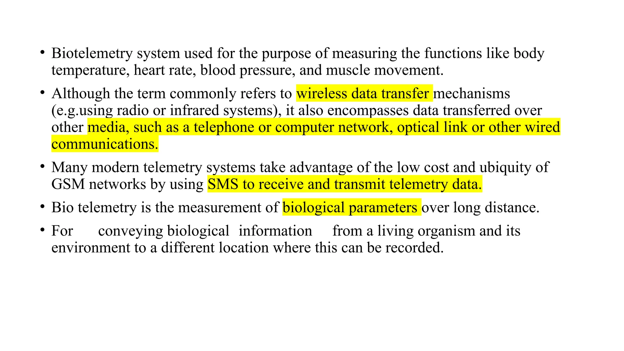
• Biotelemetry systemused for the purpose of measuring the functions like body
temperature, heart rate, blood pressure, and muscle movement.
• Although the term commonly refers to wireless data transfer mechanisms
(e.g.using radio or infrared systems), it also encompasses data transferred over
other media, such as a telephone or computer network, optical link or other wired
communications.
• Many modern telemetry systems take advantage of the low cost and ubiquity of
GSM networks by using SMS to receive and transmit telemetry data.
• Bio telemetry is the measurement of biological parameters over long distance.
• For conveying biological information from a living organism and its
environment to a different location where this can be recorded.
69.
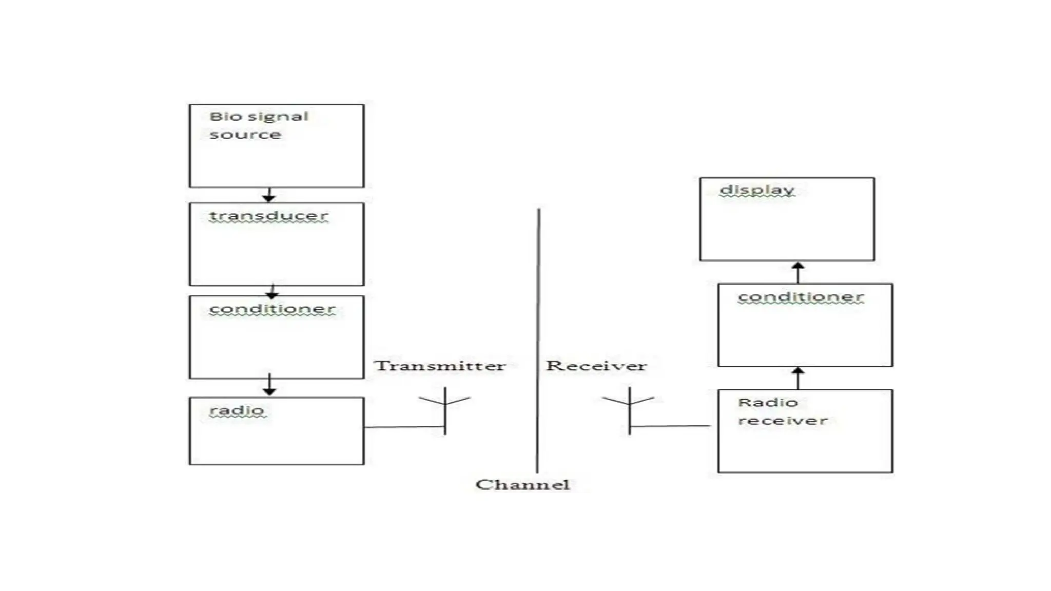
Elements of BiotelemetrySystem:
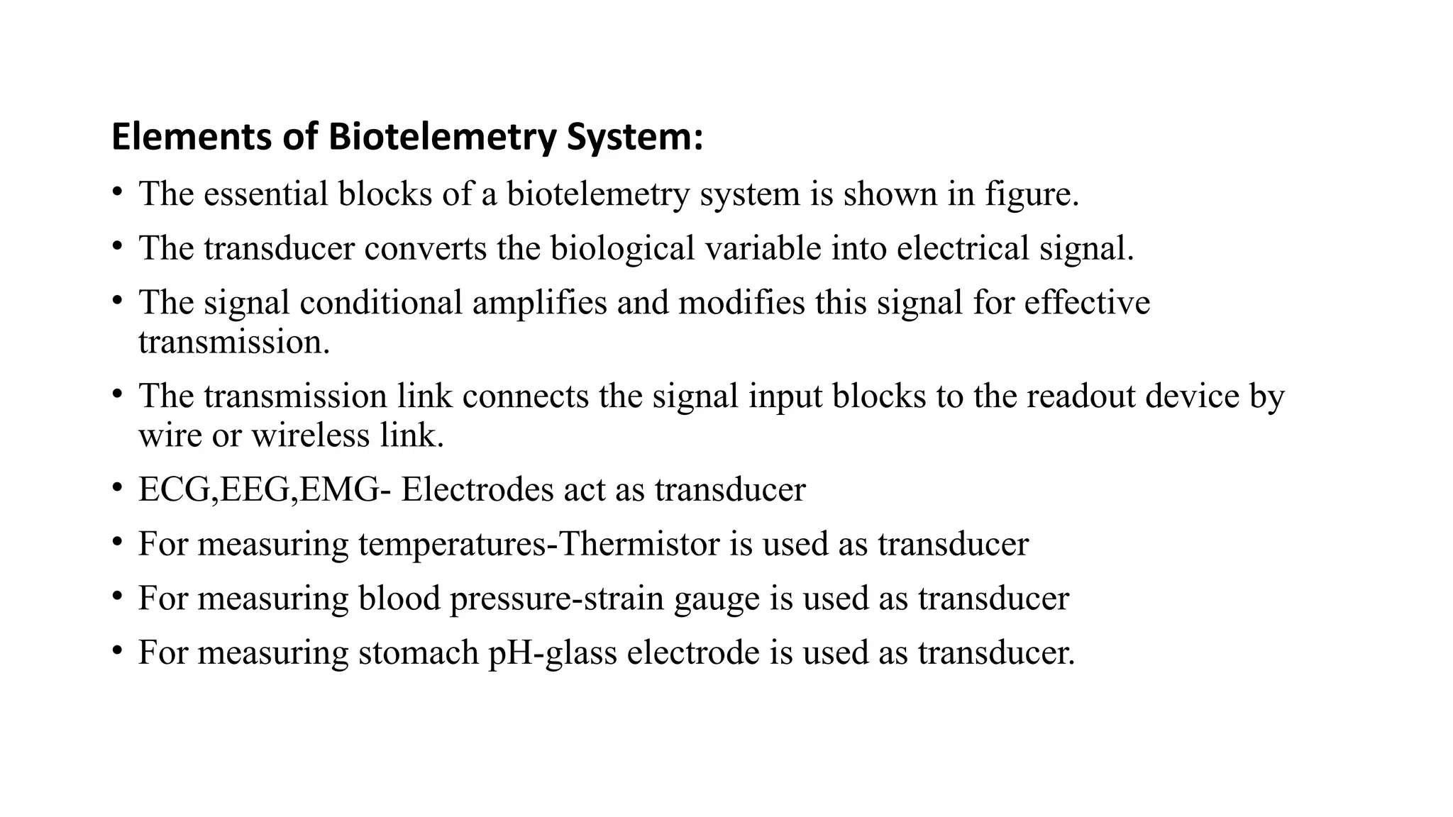
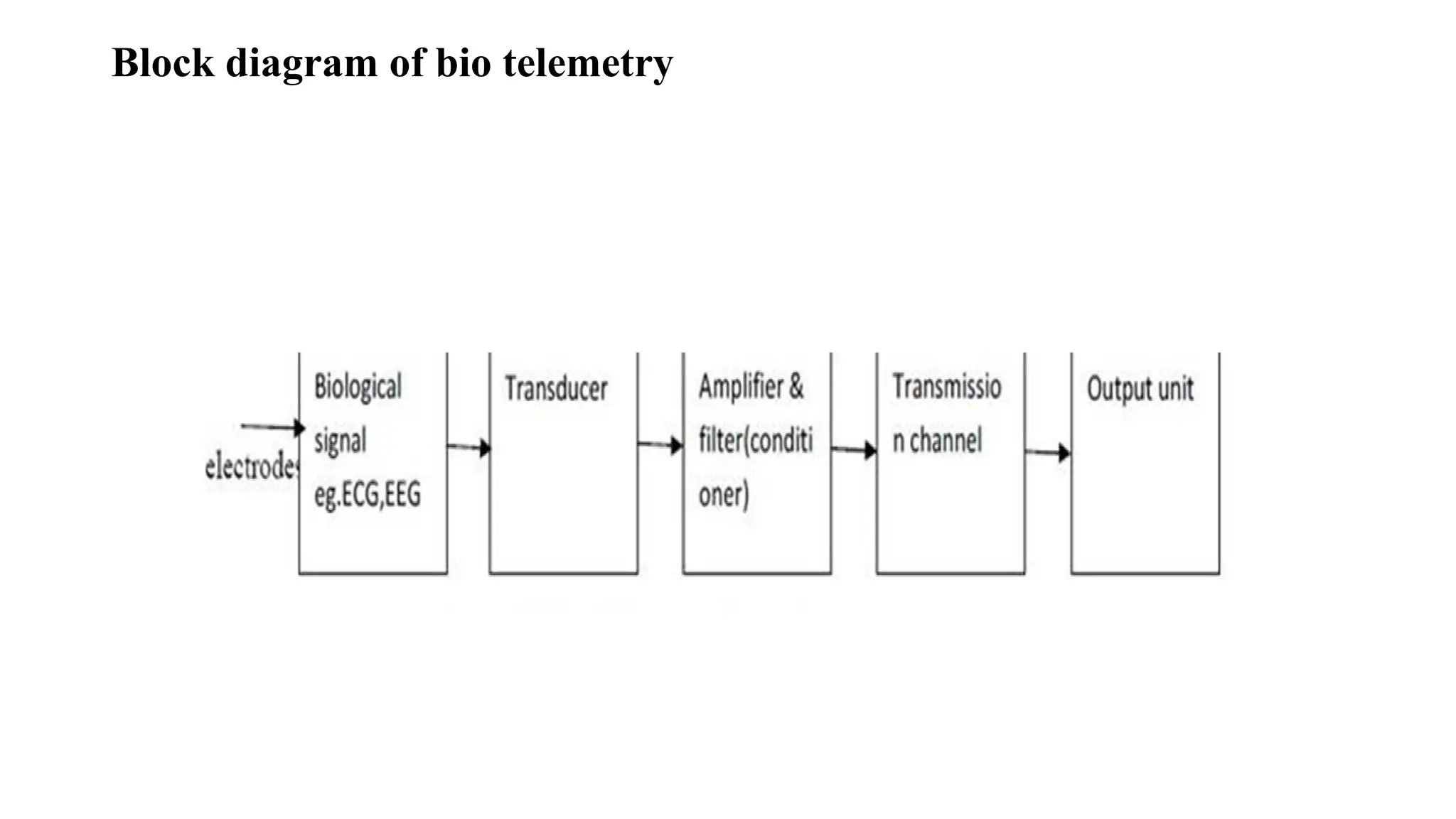
• The essential blocks of a biotelemetry system is shown in figure.
• The transducer converts the biological variable into electrical signal.
• The signal conditional amplifies and modifies this signal for effective
transmission.
• The transmission link connects the signal input blocks to the readout device by
wire or wireless link.
• ECG,EEG,EMG- Electrodes act as transducer
• For measuring temperatures-Thermistor is used as transducer
• For measuring blood pressure-strain gauge is used as transducer
• For measuring stomach pH-glass electrode is used as transducer.
DESIGN OF BIOTELEMETRY:
• Telemetry system should be selected to transmit the bio –electric Signal with maximum fidelity and
simplicity.
• The system should not affect the living system by any interference.
• Smaller in size light in weight.
• It should have more stability and reliability.
• The power consumption at the transmitter and receiver should be small.
• It should reject common mode interference rejection.
• Miniatured radio telemetry system should be used to reduce noise.
72.
RADIO TELEMETRY SYSTEMS:
•Single channel telemetry system
• Multi channel telemetry system
SINGLE CHANNEL TELEMETRY SYSTEM
• For a single channel telemetry system, a miniature battery operated radio transmitter is connected
to the electrodes of the patients.
• The transmitter broadcasts the biopotential to a remote place in which the receive detects the radio
signal and recovers signal for further processing.
• The receiving system can be located in a room separately from the patients.
•The only risk is electrical shock to the patient is due to the battery powered transmitter itself. Since
it is kept low there is negligible risk to the patient.
•The biosignals are amplified to radio frequency range of few hundred KHz to about 300 KHz and
then they are transmitted by transmitter antenna.
74.
• Further theamplitude modulation is not adapted because when relative motion
occurs between the transmitter and receiver, the signal amplitude will be varied
and thus introduces serious errors. Thus to adapt that we use either frequency
modulation or pulse modulation technique to transmit the bio signals.
• Transmission of bioelectric variables:
• In a single channel telemetry system, the measurements are made under of the two
categories:
• Active measurements
• Passive measurements
• Active measurements: Here the bioelectric variables like ECG, EMG and EEG are
measured directly without using any excitation voltage.
75.
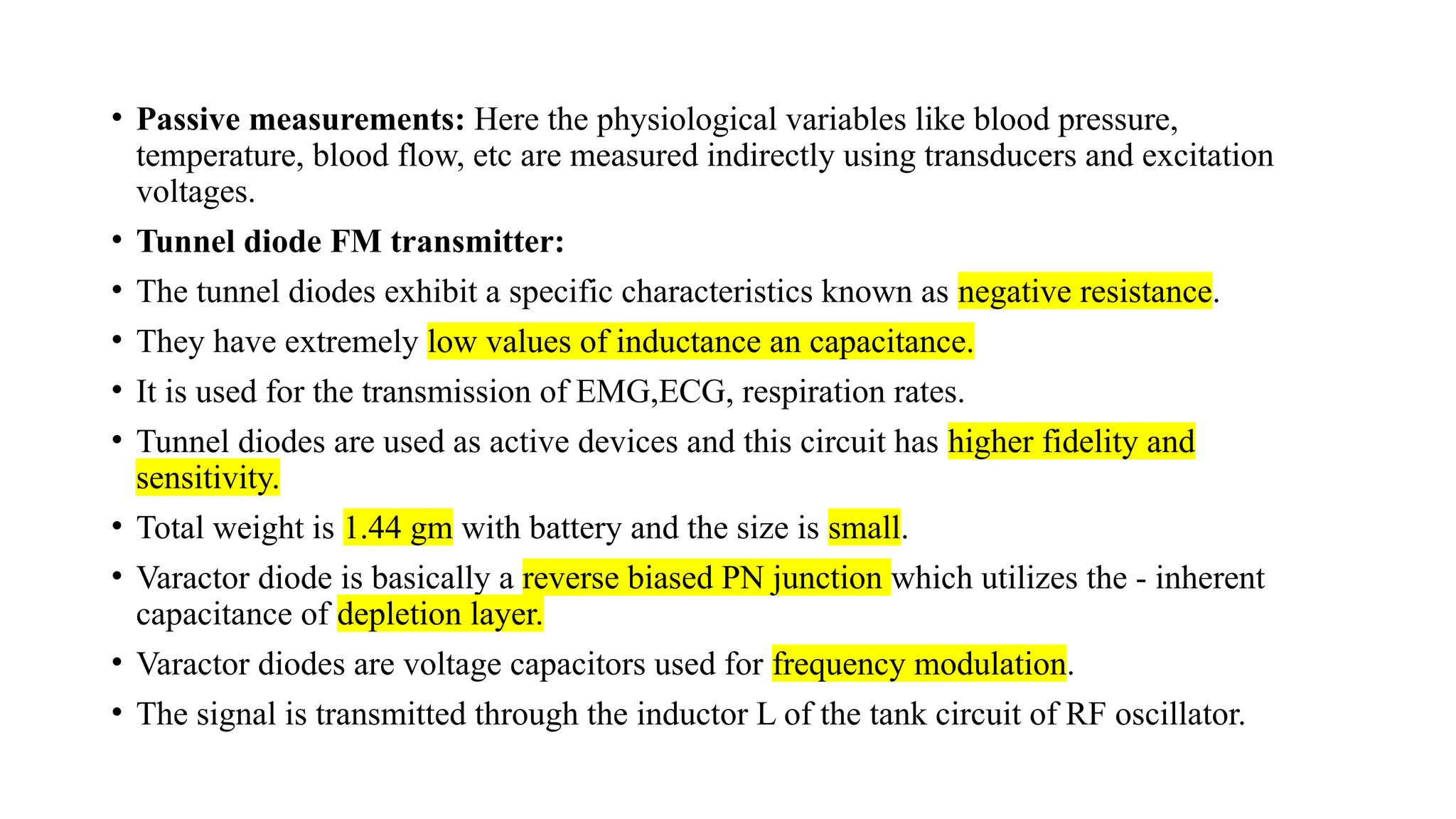
• Passive measurements:Here the physiological variables like blood pressure,
temperature, blood flow, etc are measured indirectly using transducers and excitation
voltages.
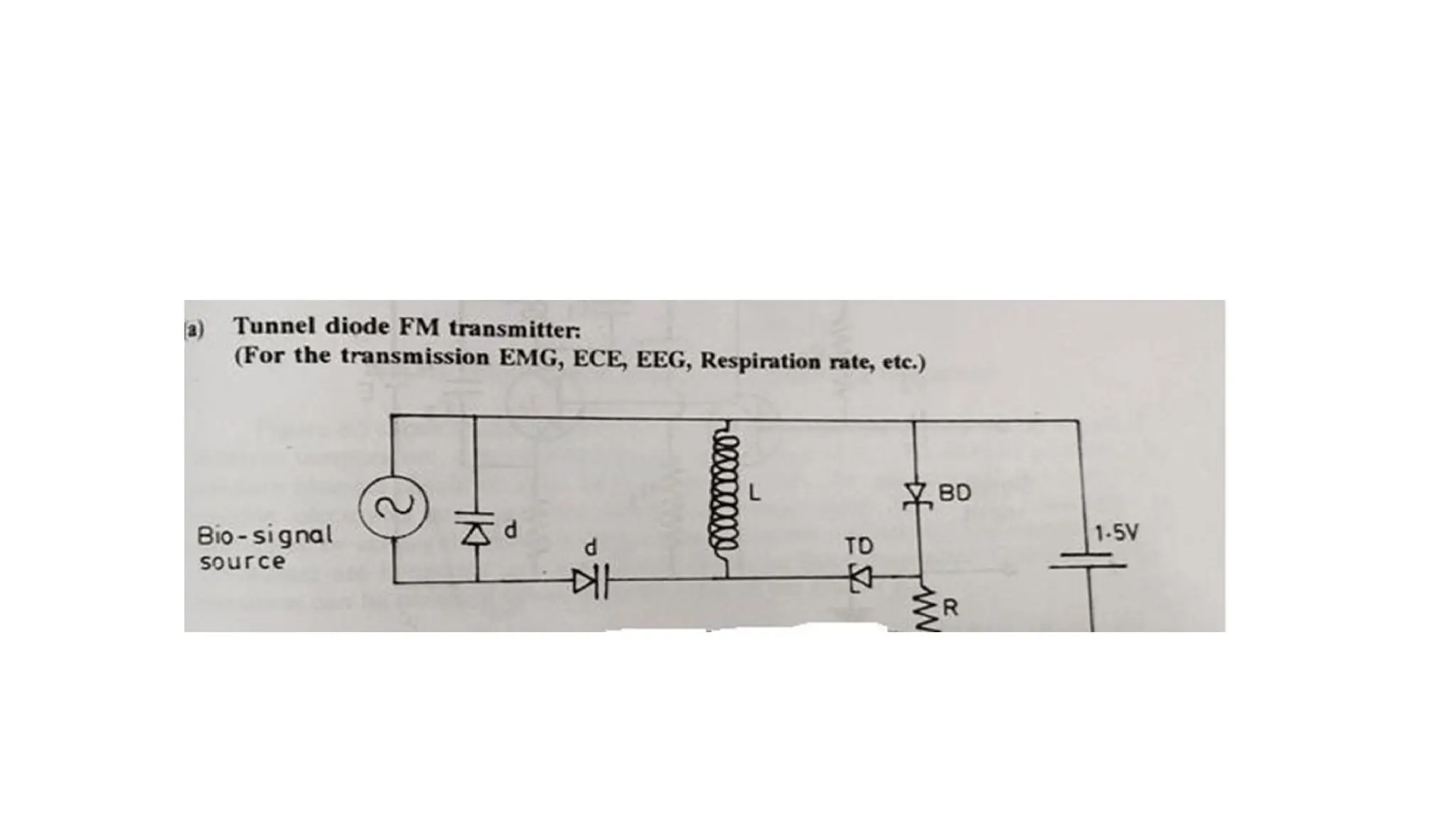
• Tunnel diode FM transmitter:
• The tunnel diodes exhibit a specific characteristics known as negative resistance.
• They have extremely low values of inductance an capacitance.
• It is used for the transmission of EMG,ECG, respiration rates.
• Tunnel diodes are used as active devices and this circuit has higher fidelity and
sensitivity.
• Total weight is 1.44 gm with battery and the size is small.
• Varactor diode is basically a reverse biased PN junction which utilizes the - inherent
capacitance of depletion layer.
• Varactor diodes are voltage capacitors used for frequency modulation.
• The signal is transmitted through the inductor L of the tank circuit of RF oscillator.
77.
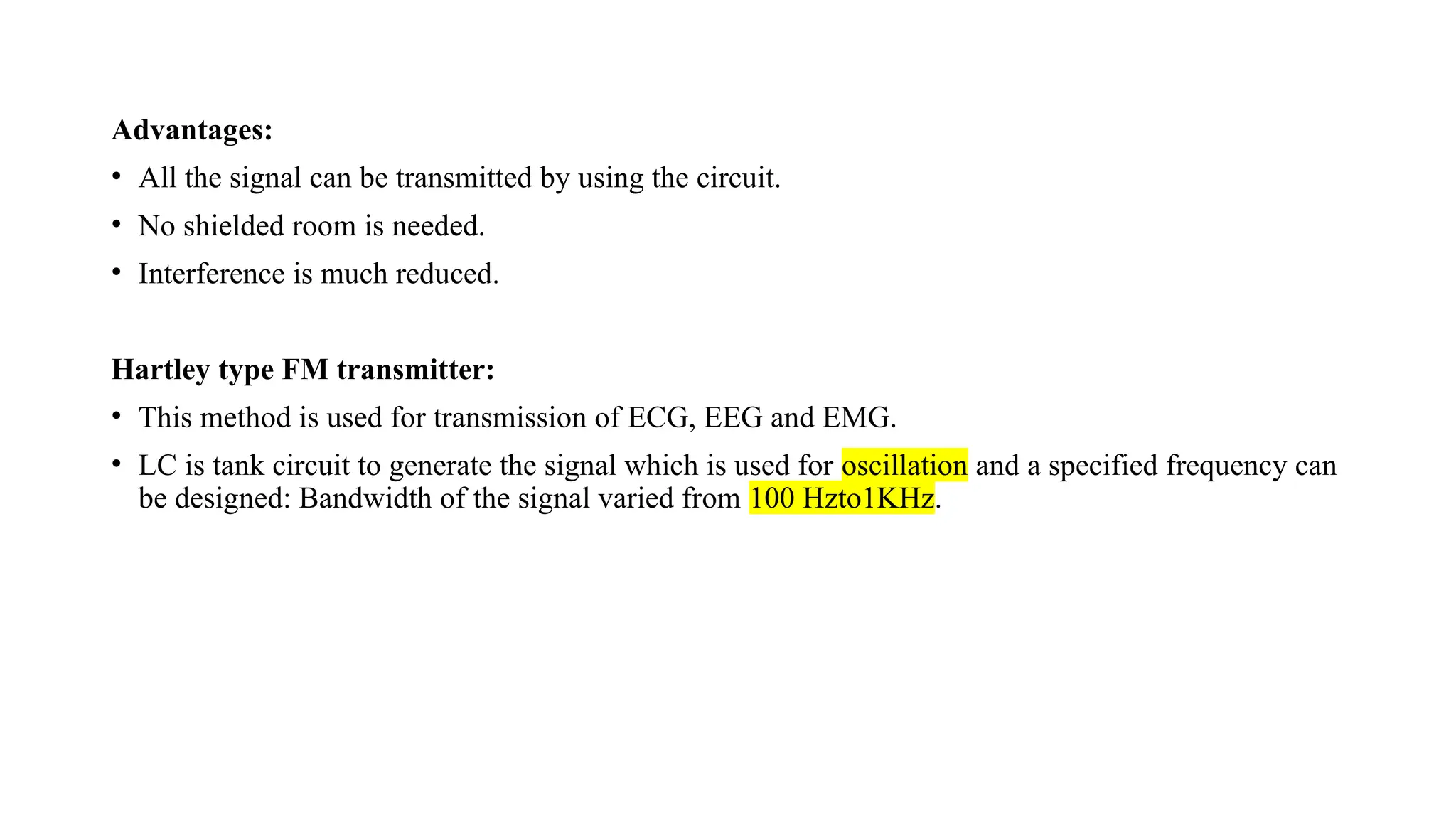
Advantages:
• All thesignal can be transmitted by using the circuit.
• No shielded room is needed.
• Interference is much reduced.
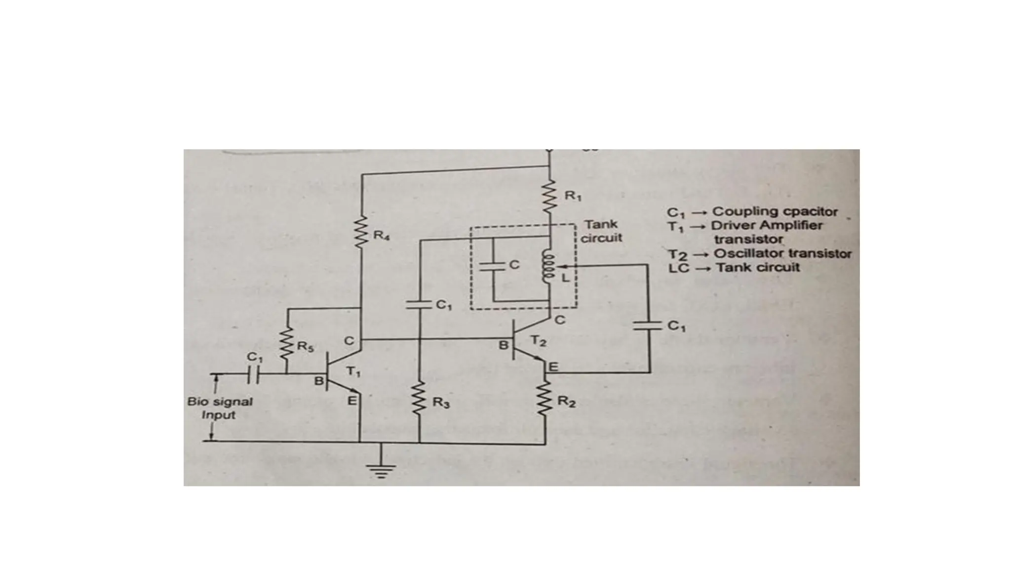
Hartley type FM transmitter:
• This method is used for transmission of ECG, EEG and EMG.
• LC is tank circuit to generate the signal which is used for oscillation and a specified frequency can
be designed: Bandwidth of the signal varied from 100 Hzto1KHz.
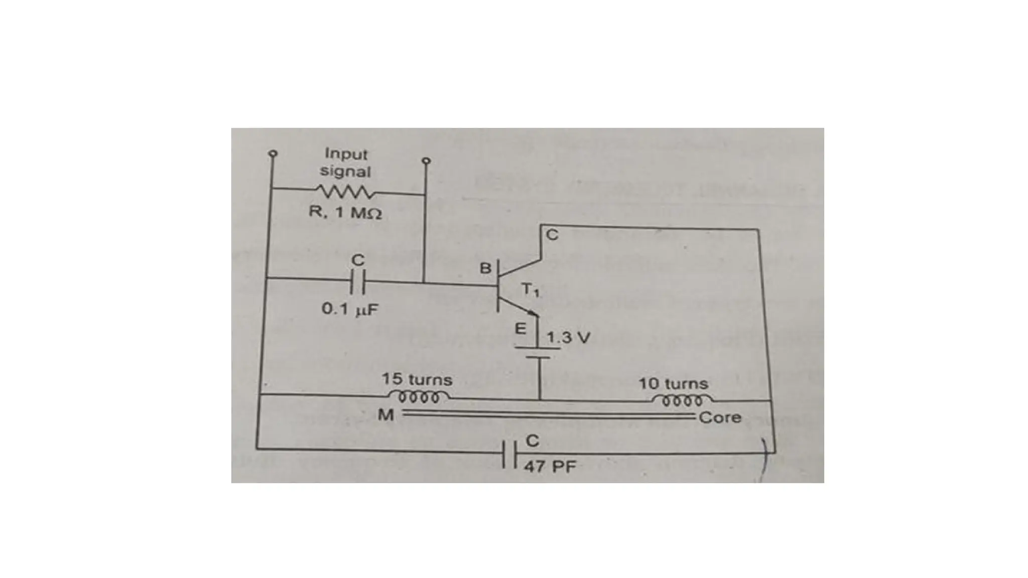
79.
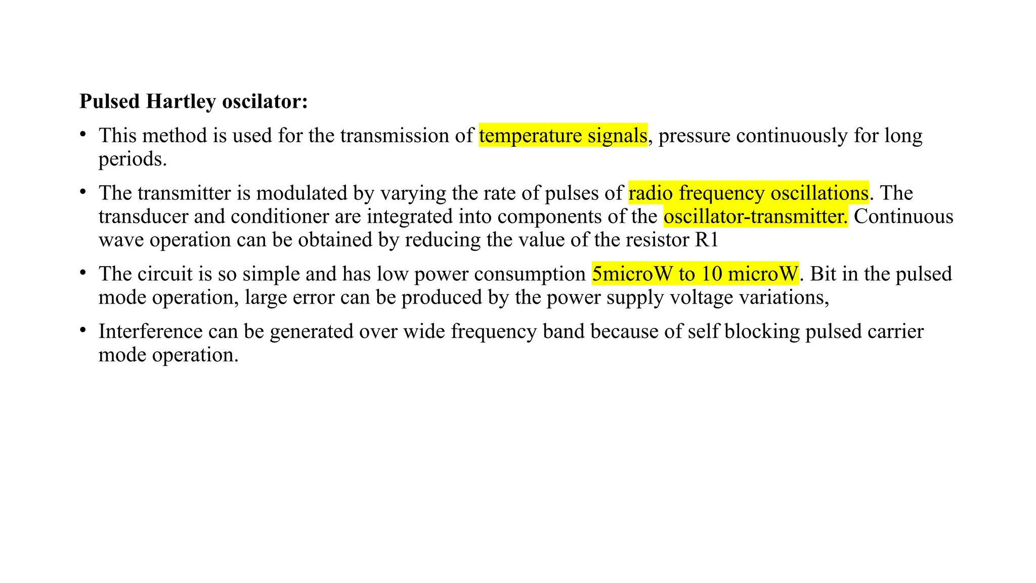
Pulsed Hartley oscilator:
•This method is used for the transmission of temperature signals, pressure continuously for long
periods.
• The transmitter is modulated by varying the rate of pulses of radio frequency oscillations. The
transducer and conditioner are integrated into components of the oscillator-transmitter. Continuous
wave operation can be obtained by reducing the value of the resistor R1
• The circuit is so simple and has low power consumption 5microW to 10 microW. Bit in the pulsed
mode operation, large error can be produced by the power supply voltage variations,
• Interference can be generated over wide frequency band because of self blocking pulsed carrier
mode operation.
81.
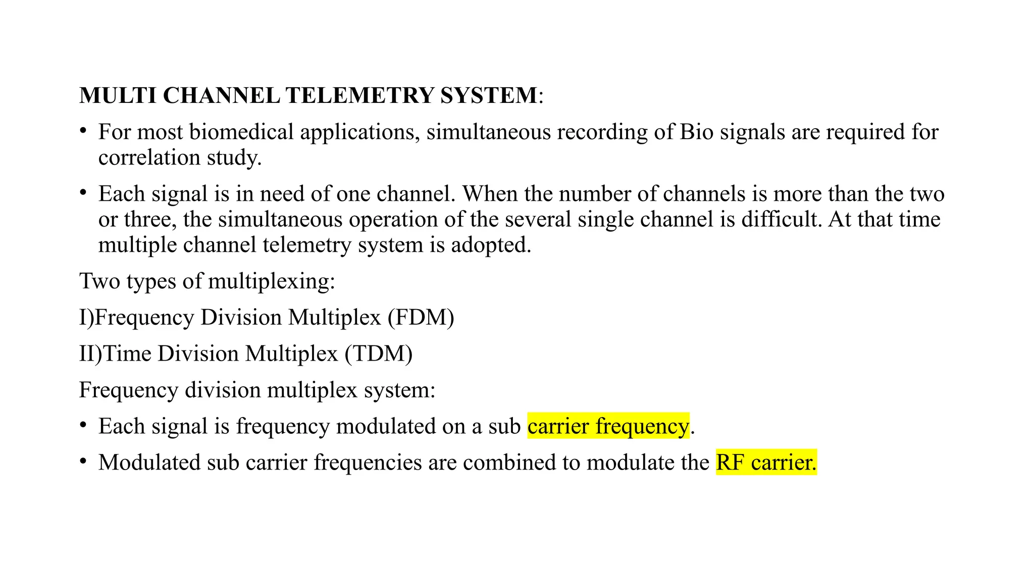
MULTI CHANNEL TELEMETRYSYSTEM:
• For most biomedical applications, simultaneous recording of Bio signals are required for
correlation study.
• Each signal is in need of one channel. When the number of channels is more than the two
or three, the simultaneous operation of the several single channel is difficult. At that time
multiple channel telemetry system is adopted.
Two types of multiplexing:
I)Frequency Division Multiplex (FDM)
II)Time Division Multiplex (TDM)
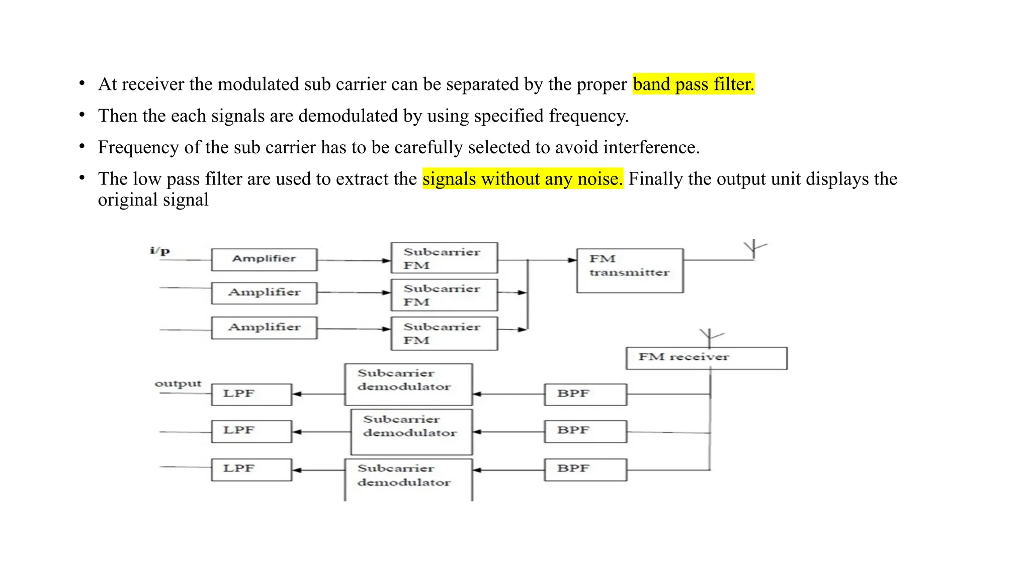
Frequency division multiplex system:
• Each signal is frequency modulated on a sub carrier frequency.
• Modulated sub carrier frequencies are combined to modulate the RF carrier.
82.
• At receiverthe modulated sub carrier can be separated by the proper band pass filter.
• Then the each signals are demodulated by using specified frequency.
• Frequency of the sub carrier has to be carefully selected to avoid interference.
• The low pass filter are used to extract the signals without any noise. Finally the output unit displays the
original signal
83.
Time division multiplextelemetry system:
• Most biomedical signals have low frequency bandwidth requirement, we can use time
division multiple system by time sharing scheme.
• Transmission channel is connected to each signal channel input for a short time to sample
and transmit that signal.
• Transmitter is switched to the next input signal channel in a definite sequence.
• All the channels have been scanned once, a cycle is completed and the next cycle will
start. Scanning follows a order from signal 1 to signal 3.
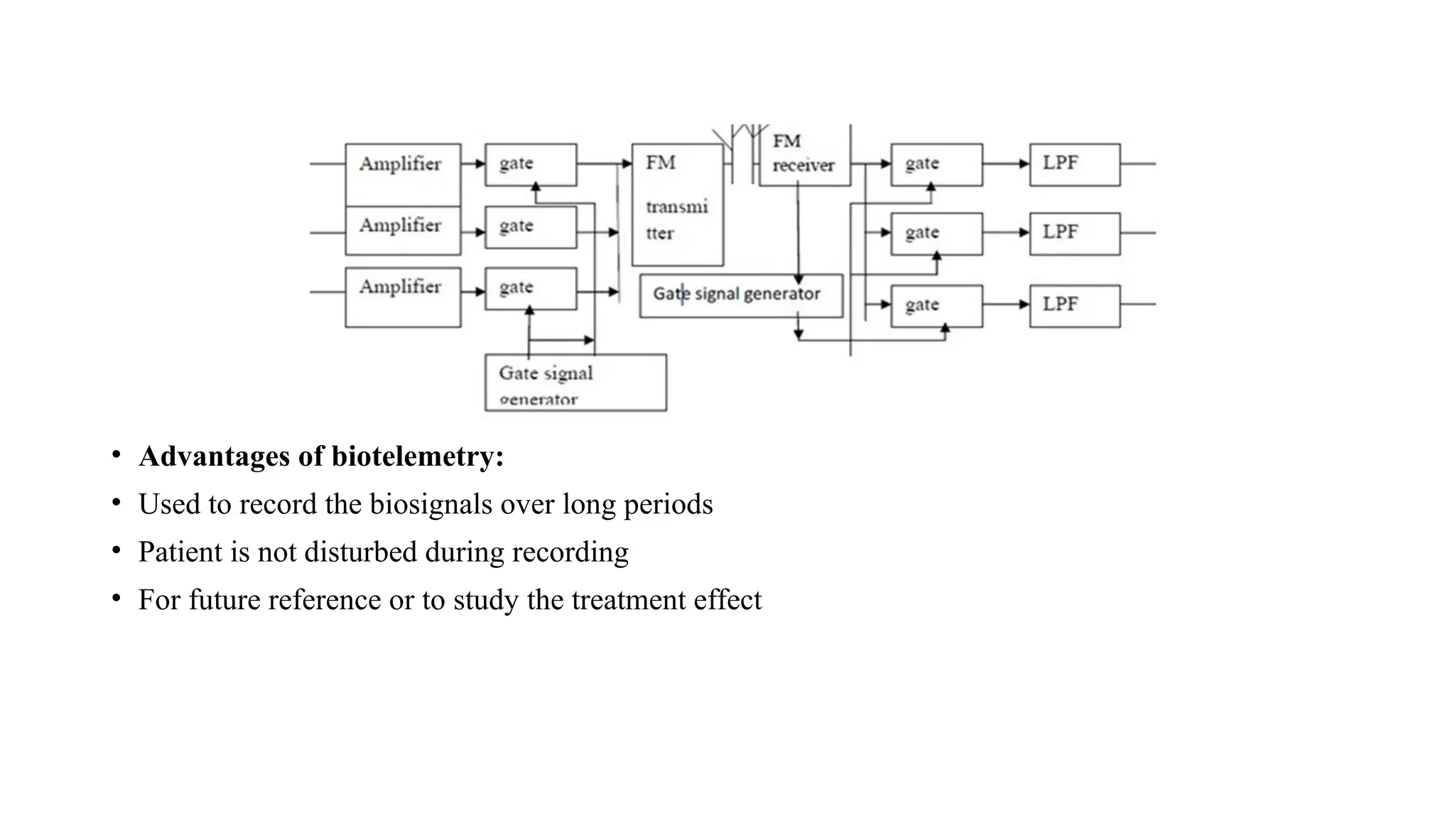
• At the receiver the process is reversed. The sequentially arranged, signal pulses are given
to the individual channels by using gate signal generator.
• If the number of scanning cycles per second is large and if the transmitter and the receiver
are synchronized, the signal in each channel at the receiver side can be recovered.
• But the scanning frequency fn has to satisfy the following condition i.e) The scanning frequency
fn should be atleast greater than twice the maximum signal frequency fs .fscan >2fmax
84.
• Advantages ofbiotelemetry:
• Used to record the biosignals over long periods
• Patient is not disturbed during recording
• For future reference or to study the treatment effect
85.
Multi-patient telemetry
• Multi-patienttelemetry" refers to a system in which multiple patients' vital signs and
physiological data are continuously and remotely monitored from a single central station.
This approach is a core component of modern hospital care, particularly in telemetry units,
intensive care units (ICUs), and emergency rooms.
Key Aspects of Multi-Patient Telemetry
• Centralized Surveillance: Data from individual, often mobile, patient-worn transmitters are sent
wirelessly to a central monitoring system. A trained healthcare provider or telemetry technician at
this station can observe the data for all monitored patients simultaneously.
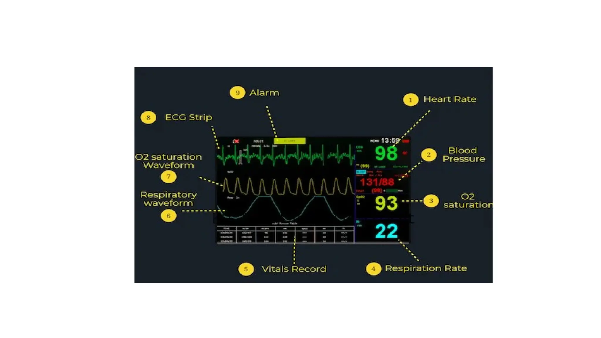
• Real-time Data Access: Clinicians have immediate access to real-time vital sign parameters,
waveforms (like ECG and SpO2), and alarm conditions, either on the central monitor, a hospital
PC, or a mobile device/tablet via a secure network.
• Efficiency and Workflow: This system allows for the efficient monitoring of a large patient
population, streamlining clinical workflows and enabling medical staff to quickly identify and
prioritize patients who need immediate intervention.
86.
• Patient Mobility:The use of small, battery-powered, wearable transmitters allows patients to be
ambulatory (move around the ward) while still being continuously monitored, rather than being
restricted to a bedside monitor.
• Alarm Management: The system generates alarms for abnormal heart rhythms or other critical
changes in condition, which helps staff respond quickly to potential problems. Effective alarm
management is crucial to prevent "alarm fatigue" among staff.
• Data Integration: Patient data from telemetry can be integrated into the patient's electronic medical
record (EMR) for a seamless and comprehensive patient history.
• Common Monitored Parameters
• Typical data collected and transmitted in a multi-patient telemetry system can include:
• Electrocardiogram (ECG) for heart rate and rhythm
• Oxygen saturation (SpO2)
• Respiration rate
• Non-invasive blood pressure (NIBP)
• Temperature
• These systems are vital for managing patients with various conditions, including arrhythmias, heart
failure, post-cardiac surgery recovery, and those in critical care units.
87.
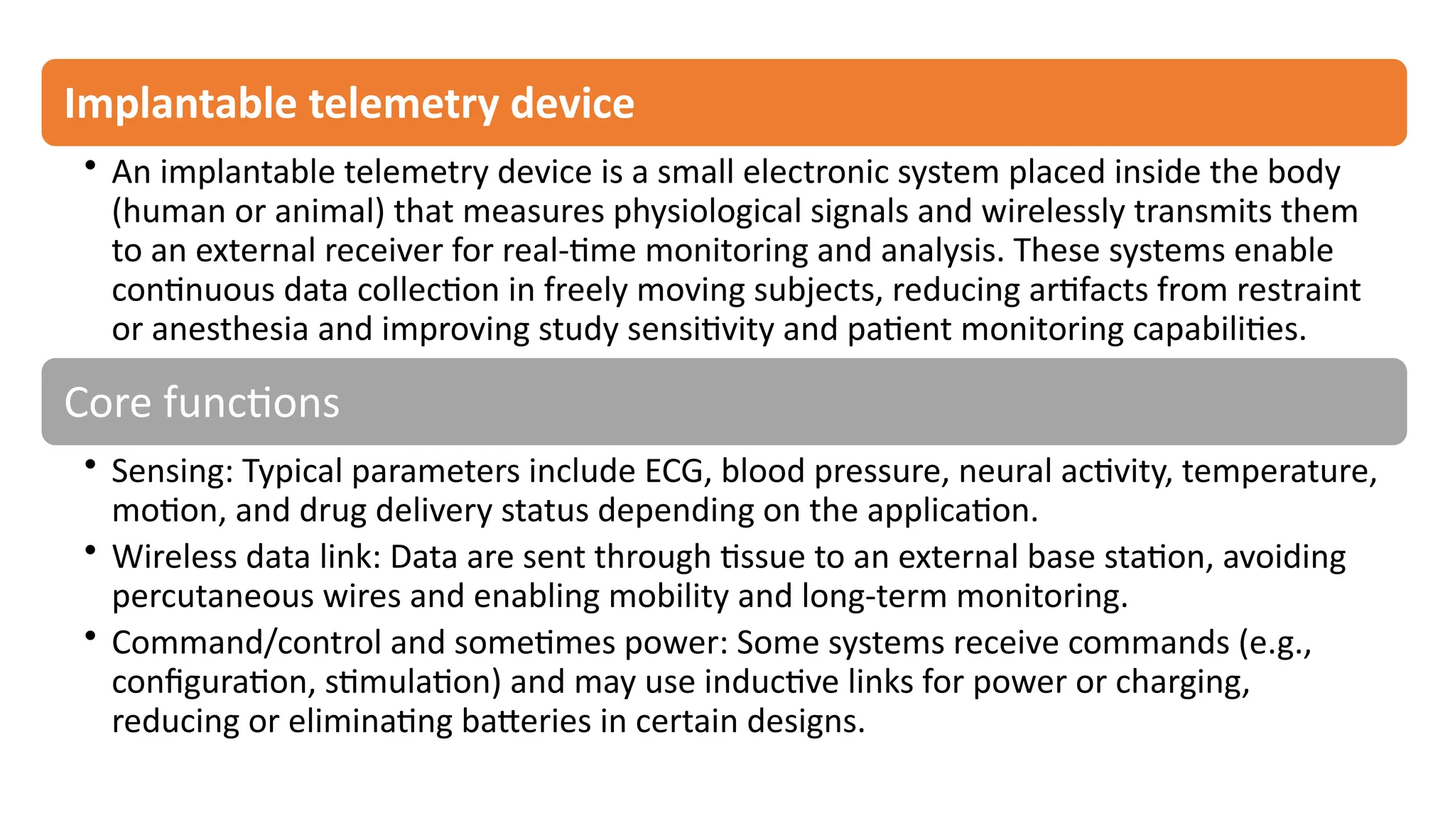
Implantable telemetry device
•An implantable telemetry device is a small electronic system placed inside the body
(human or animal) that measures physiological signals and wirelessly transmits them
to an external receiver for real-time monitoring and analysis. These systems enable
continuous data collection in freely moving subjects, reducing artifacts from restraint
or anesthesia and improving study sensitivity and patient monitoring capabilities.
Core functions
• Sensing: Typical parameters include ECG, blood pressure, neural activity, temperature,
motion, and drug delivery status depending on the application.
• Wireless data link: Data are sent through tissue to an external base station, avoiding
percutaneous wires and enabling mobility and long-term monitoring.
• Command/control and sometimes power: Some systems receive commands (e.g.,
configuration, stimulation) and may use inductive links for power or charging,
reducing or eliminating batteries in certain designs.
90.
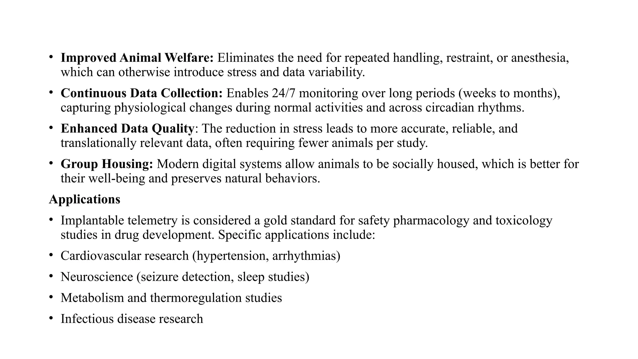
• Improved AnimalWelfare: Eliminates the need for repeated handling, restraint, or anesthesia,
which can otherwise introduce stress and data variability.
• Continuous Data Collection: Enables 24/7 monitoring over long periods (weeks to months),
capturing physiological changes during normal activities and across circadian rhythms.
• Enhanced Data Quality: The reduction in stress leads to more accurate, reliable, and
translationally relevant data, often requiring fewer animals per study.
• Group Housing: Modern digital systems allow animals to be socially housed, which is better for
their well-being and preserves natural behaviors.
Applications
• Implantable telemetry is considered a gold standard for safety pharmacology and toxicology
studies in drug development. Specific applications include:
• Cardiovascular research (hypertension, arrhythmias)
• Neuroscience (seizure detection, sleep studies)
• Metabolism and thermoregulation studies
• Infectious disease research
91.
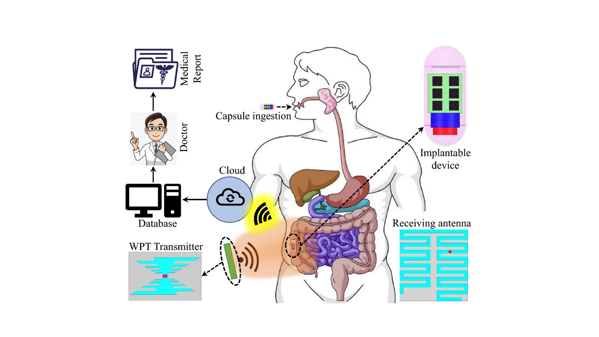
System Components
• Atypical system comprises several parts:
• Implantable Sensor Module: The device surgically placed inside the body containing the sensors
and a wireless transmitter.
• External Receiver/Transceiver: Hardware located in or near the animal's environment to capture
the wireless signals.
• Data Acquisition Software: Computer software (e.g., Ponemah software) that processes, visualizes,
and stores the incoming data.
• Power Management: Implants are typically battery-powered (sometimes rechargeable via
induction through the skin) or utilize wireless inductive charging systems to eliminate battery life
constraints.
92.
Transmission of AnalogPhysiological Signals, Over Telephone, Telemedicine.
• Transmission of analog physiological signals over telephone lines was an early
method used in telemedicine. This was accomplished by converting the analog
signals into a format suitable for the Plain Old Telephone Service (POTS)
network, typically using a modem to modulate the data for transmission.
Methods of Transmission
• Historically, the transmission process involved several steps:
• Signal Acquisition: Biosensors (e.g., ECG, blood pressure, temperature) acquired
the raw analog physiological data from the patient.
• Modulation: The analog physiological signal was either directly converted to an
audio-frequency signal (e.g., in early systems using acoustic couplers) or, more
commonly in later systems, digitized by an analog-to-digital (A/D) converter.
• A modem then modulated this data (whether analog or digitized) into an analog
electrical signal suitable for the limited bandwidth of standard telephone lines.
93.
• Transmission: Themodulated signal was transmitted over the public switched
telephone network (PSTN).
• Demodulation/Reception: At the receiving end (e.g., a medical center), a modem
demodulated the analog signal back into its original form (analog or digital), which
was then processed and displayed for the medical professional.
Limitations
• The primary limitation of using analog telephone lines for telemedicine was the
limited bandwidth (typically up to 56 kbps for modems). This limited the amount and
quality of data that could be sent, leading to issues such as:
• Lower quality of service (QoS)
• Potential for significant video and audio degradation
• Need for data compression techniques, especially for multi-channel signals like a 12-
lead ECG
• Transmission delays due to retransmission requirements when errors occurred
94.
Modern Telemedicine
• Moderntelemedicine systems primarily use digital communication technologies
such as the Internet, cellular networks (GPRS, 3G, 4G, 5G), and satellite links,
which offer significantly higher bandwidth and reliability.
• These systems typically digitize the signals at the source and use advanced
compression techniques before transmission, allowing for real-time monitoring
and high-quality data transfer.
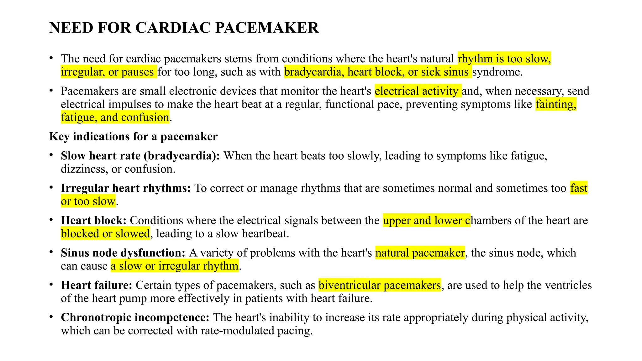
NEED FOR CARDIACPACEMAKER
• The need for cardiac pacemakers stems from conditions where the heart's natural rhythm is too slow,
irregular, or pauses for too long, such as with bradycardia, heart block, or sick sinus syndrome.
• Pacemakers are small electronic devices that monitor the heart's electrical activity and, when necessary, send
electrical impulses to make the heart beat at a regular, functional pace, preventing symptoms like fainting,
fatigue, and confusion.
Key indications for a pacemaker
• Slow heart rate (bradycardia): When the heart beats too slowly, leading to symptoms like fatigue,
dizziness, or confusion.
• Irregular heart rhythms: To correct or manage rhythms that are sometimes normal and sometimes too fast
or too slow.
• Heart block: Conditions where the electrical signals between the upper and lower chambers of the heart are
blocked or slowed, leading to a slow heartbeat.
• Sinus node dysfunction: A variety of problems with the heart's natural pacemaker, the sinus node, which
can cause a slow or irregular rhythm.
• Heart failure: Certain types of pacemakers, such as biventricular pacemakers, are used to help the ventricles
of the heart pump more effectively in patients with heart failure.
• Chronotropic incompetence: The heart's inability to increase its rate appropriately during physical activity,
which can be corrected with rate-modulated pacing.
97.
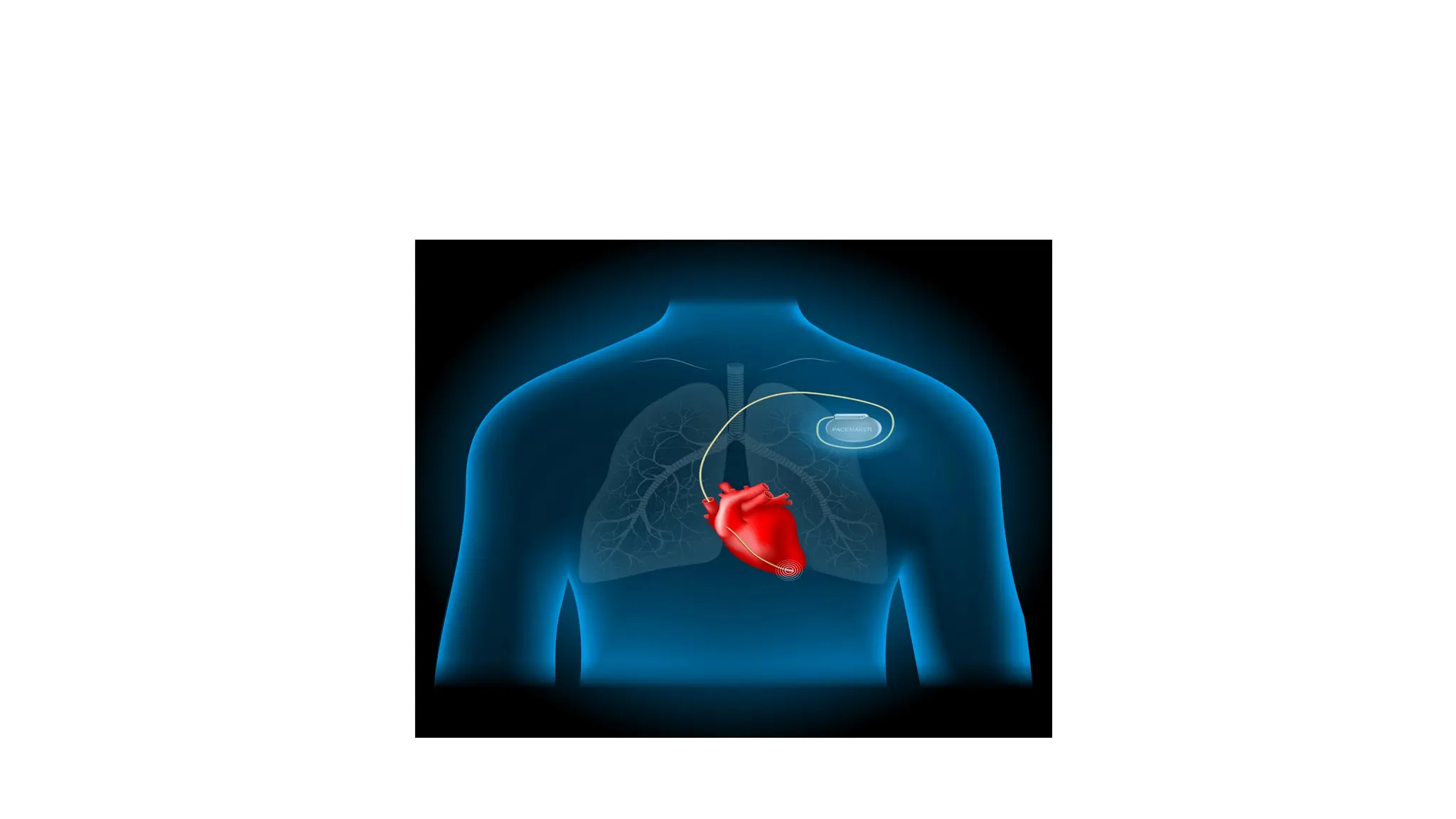
How they work
•A modern permanent pacemaker consists of a generator, which contains a battery
and circuitry, and one or more leads (insulated wires) that are threaded through
veins into the heart.
• The device continuously senses the heart's natural electrical activity.
• If it detects that the heart is beating too slowly, it sends a small, imperceptible
electrical impulse to stimulate the heart muscle to contract.
• Many pacemakers can also be programmed to increase pacing when the patient
becomes more active, ensuring the heart keeps up with the body's demands.
98.
Advancements in theField
• The field of cardiac rhythm management has seen continuous technological
advancements, including:
• Leadless Pacemakers: These devices are a single unit, about the size of a large
pill, implanted directly into the heart chamber via a catheter in the leg, eliminating
the need for leads and a chest incision.
• Remote Monitoring: Many devices allow data to be transmitted wirelessly to a
patient's healthcare team, enabling device checks and early detection of issues
without frequent in-person clinic visits.
• MRI-Conditional Devices: Modern pacemakers are often designed to be safe for
use during magnetic resonance imaging (MRI) procedures, subject to specific
conditions.
100.
IMPLANTABLE PACEMAKER
• Apacemaker is a small, battery-powered device that prevents the heart from
beating too slowly. You need surgery to get a pacemaker. The device is placed
under the skin near the collarbone.
• A pacemaker also is called a cardiac pacing device.
• There are different types of pacemakers.
• Single chamber pacemaker. This type usually sends electrical signals to the
lower right chamber of the heart.
• Dual chamber pacemaker. This type sends electrical signals to the upper and
lower right heart chambers.
• Biventricular pacemaker. This type also is called a cardiac resynchronization
pacemaker. It's for people who have heart failure and a slow heartbeat. The device
stimulates both lower heart chambers. It helps make the heart muscle stronger.
101.
A pacemaker isused to control or increase the heartbeat.
It stimulates the heart as needed to keep it beating regularly.
The heart's electrical system typically controls the heartbeat.
Electrical signals, called impulses, move through the heart chambers. They tell the heart when to
beat.
Changes in heart signaling may happen if the heart muscle is damaged.
Changes in genes before birth and some medicines also can cause changes in heart signaling.
You may need a pacemaker if:
You have a slow or irregular heartbeat that lasts for a long time.
You have heart failure.
102.
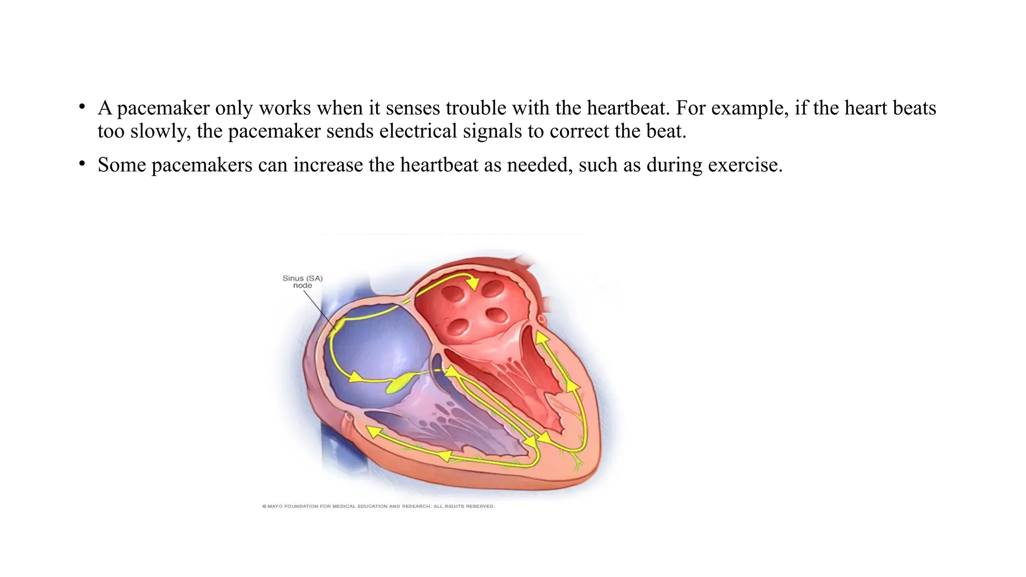
• A pacemakeronly works when it senses trouble with the heartbeat. For example, if the heart beats
too slowly, the pacemaker sends electrical signals to correct the beat.
• Some pacemakers can increase the heartbeat as needed, such as during exercise.
103.
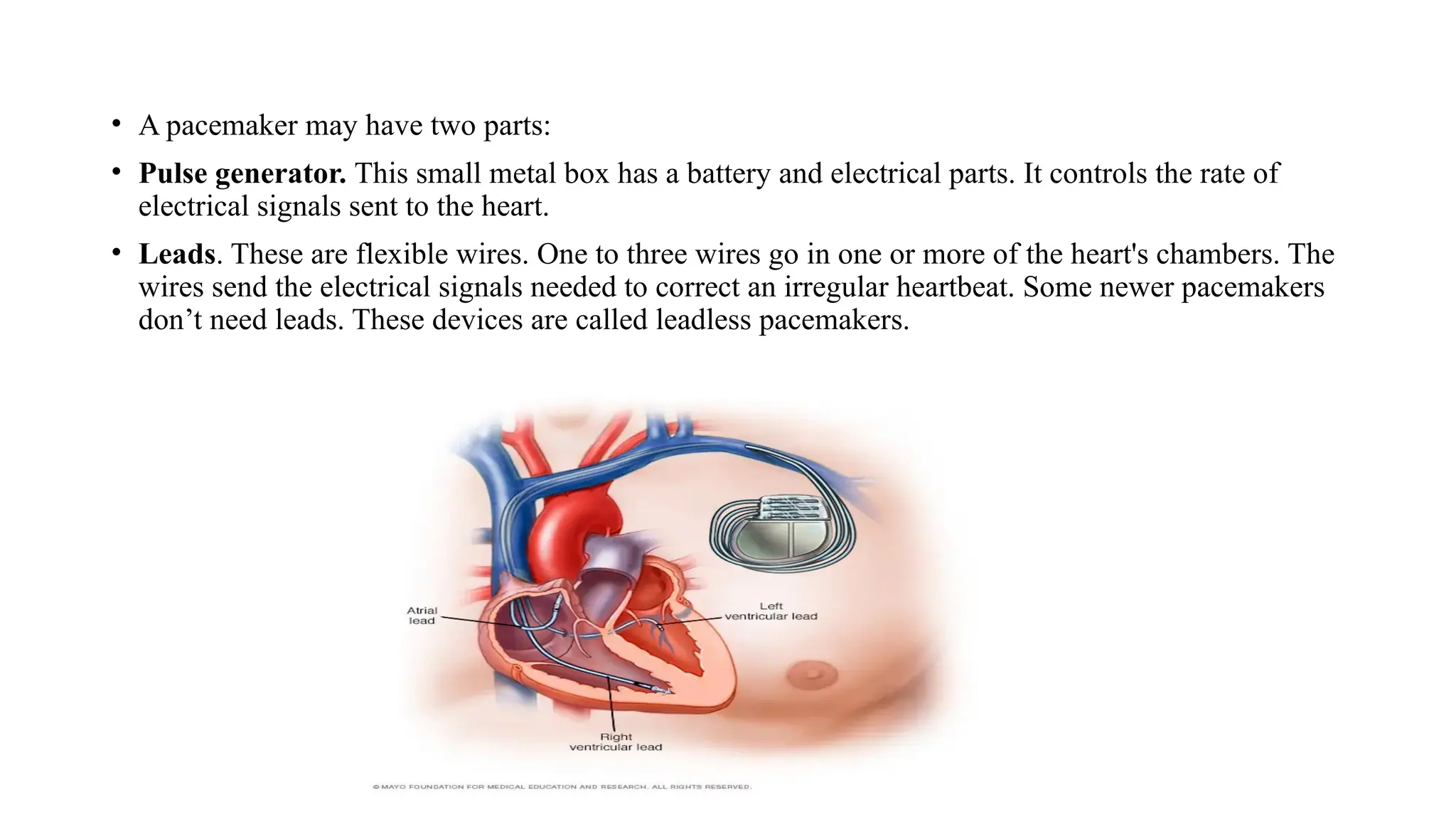
• A pacemakermay have two parts:
• Pulse generator. This small metal box has a battery and electrical parts. It controls the rate of
electrical signals sent to the heart.
• Leads. These are flexible wires. One to three wires go in one or more of the heart's chambers. The
wires send the electrical signals needed to correct an irregular heartbeat. Some newer pacemakers
don’t need leads. These devices are called leadless pacemakers.
104.
DC DEFIBRILATOR
• ADefibrillator is an electronic device that creates a sustained myocardial depolarization
of a patients heart in order to stop ventricular fibrillation or atrial fibrillation.
• Ventricular fibrillation is a serious cardiac emergency resulting from asynchronous
contraction of heart muscles.
• This results from electric shock or abnormalities of body chemistry. Hence it cause a
steep fall of cardiac output and can lead to death if adequate steps are not taken promptly.
• Ventricular fibrillation can be converted to a more efficient rhythm by applying a high
voltage shock to the heart.
• This voltage causes all muscle fibers to contract simultaneously. The instrument for
administering the electric shock is called defibrillator.
• The sudden cardiac arrest can be treated using a defibrillator and 80% of patients will be
cured if the treatment is given within one minute of attack.
• An atrial fibrillation causes reduced cardiac output but is usually not fatal. It happens for
the young people who are always smoking and can even be cured by drug therapy.
105.
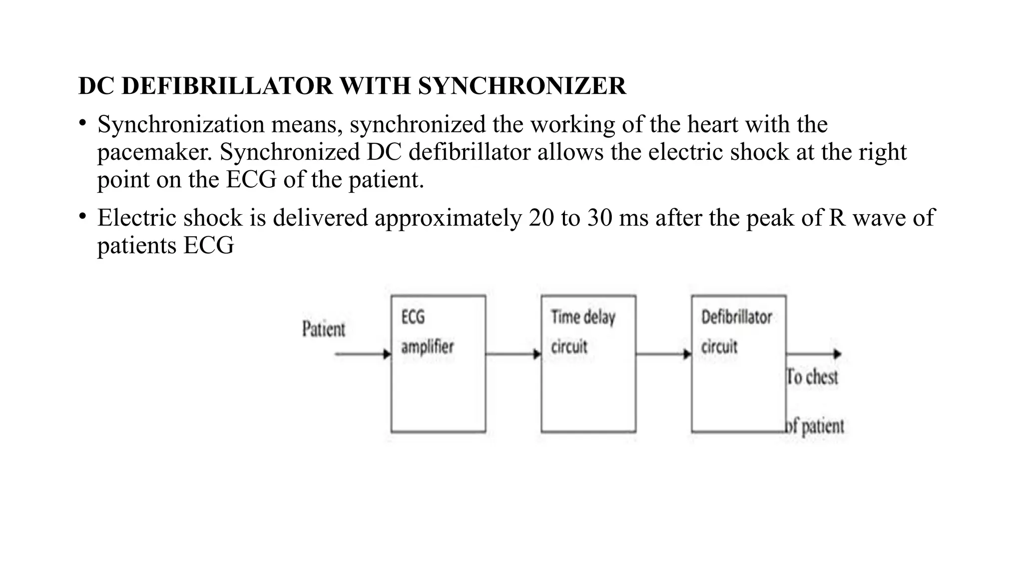
DC DEFIBRILLATOR WITHSYNCHRONIZER
• Synchronization means, synchronized the working of the heart with the
pacemaker. Synchronized DC defibrillator allows the electric shock at the right
point on the ECG of the patient.
• Electric shock is delivered approximately 20 to 30 ms after the peak of R wave of
patients ECG
106.
• ECG waveformis traced from the patient.
• R-wave in the output of ECG amplifier triggers the time delay circuit .It gives the
delay of 30 ms approximately. After that, defibrillator circuit is switched ON. So
that, the capacitor discharges the electric shock to the patient’s heart.
• The moment at which electric shock occurs is noted by producing the marker pulse
on monitoring display.
• This type of circuit is preferred in cardiac emergencies.
• The sudden cardiac arrest can be treated using a defibrillator and 80 percent of the
patients will be cured from the cardiac arrest if the is given within one minute of
the attack.
Electrodes used for defibrillation
• These paddles have metal disks of 8 to 10 cm in diameter for external use.
• For internal use smaller paddles are used on infants and children.
• For external use, pair of electrodes are firmly pressed against the patients chest.
107.
Need of InsulationHandle
• To prevent the person applying the electrodes from accidential electric shock specially
insulated handles are provided in the paddles.
• When paddles are properly positioned , this prevents the patient from receiving a shock.
• In earlier equipment a foot switch is used instead of thumb switch.
Need of Thumb Switch
• There is a possibility of someone accidentally stepping on the foot switch in the
excitement of an emergency before the paddles are placed. So thumb switches are
mostly preferred.
Charging of Defibrillators
• In some defibrillators charging is done by means of a charge switch located in the front
panel of the unit.
• The charge switch is located in the handle of one of its paddles.
• In few defibrillators the charging process begins automatically after discharge.
108.
• Types ofElectrodes
Two electrodes are
• Anterior-anterior
• Anterior-posterior
• Anterior-anterior paddles are applied to the chest.
• Anterior-posterior paddles are applied to both the patients chest wall and back so that energy is
delivered through the heart.
• Specially designed pediatric paddles are available with diameter ranging from 2 to 6 .Internal
paddles can be either gas-sterilized or autoclaved.
• Indication Meter
• Most of the defibrillators include a watt second meter to inducate the amount of energy stored in
the capacitor before discharge.
• The energy indicated on the meter is lost or dissipated as heat in the components inside the unit.
109.
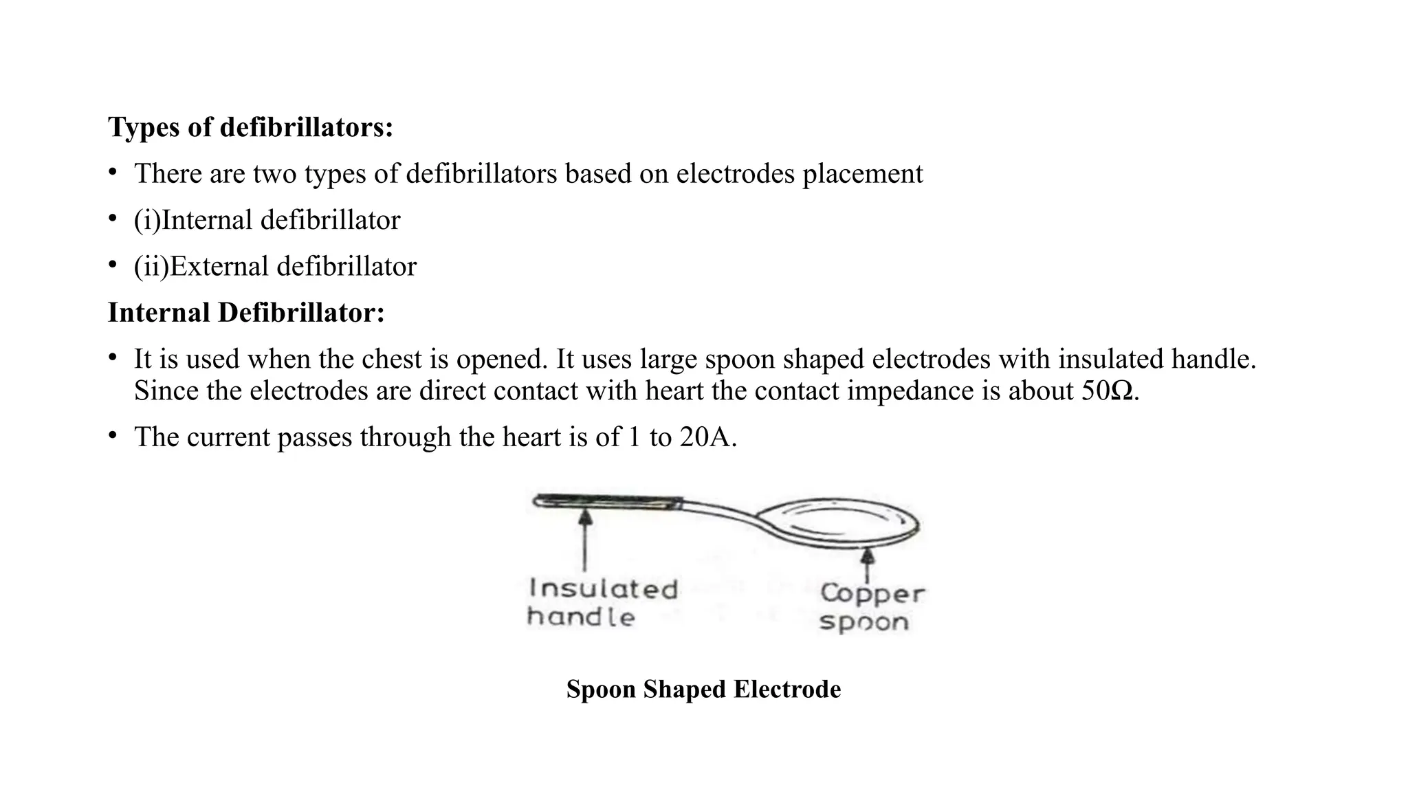
Types of defibrillators:
•There are two types of defibrillators based on electrodes placement
• (i)Internal defibrillator
• (ii)External defibrillator
Internal Defibrillator:
• It is used when the chest is opened. It uses large spoon shaped electrodes with insulated handle.
Since the electrodes are direct contact with heart the contact impedance is about 50Ω.
• The current passes through the heart is of 1 to 20A.
Spoon Shaped Electrode
110.
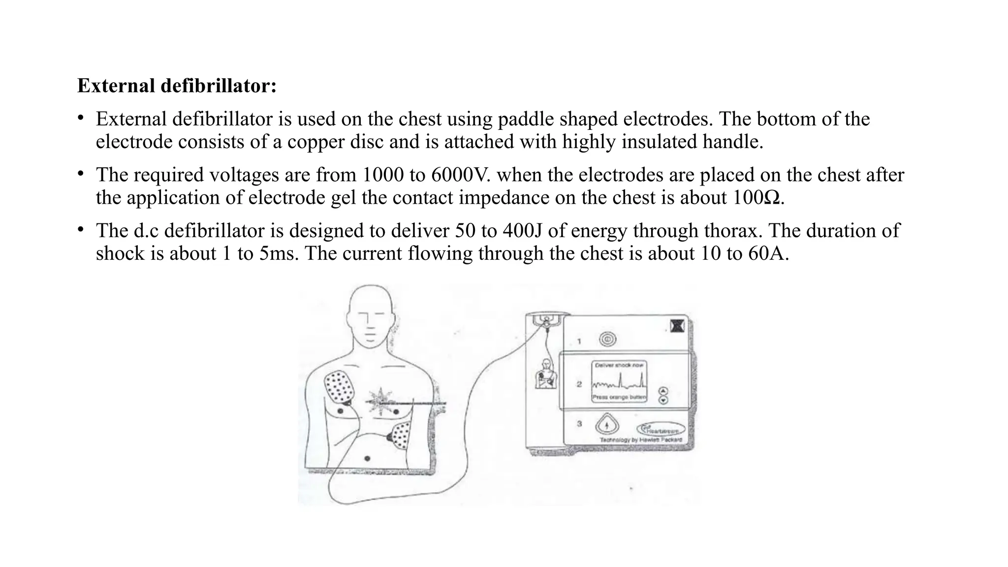
External defibrillator:
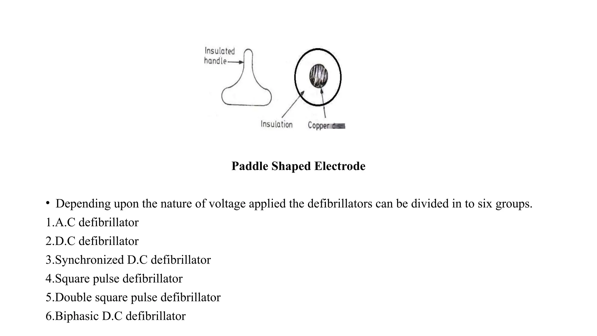
• Externaldefibrillator is used on the chest using paddle shaped electrodes. The bottom of the
electrode consists of a copper disc and is attached with highly insulated handle.
• The required voltages are from 1000 to 6000V. when the electrodes are placed on the chest after
the application of electrode gel the contact impedance on the chest is about 100Ω.
• The d.c defibrillator is designed to deliver 50 to 400J of energy through thorax. The duration of
shock is about 1 to 5ms. The current flowing through the chest is about 10 to 60A.
111.
Paddle Shaped Electrode
•Depending upon the nature of voltage applied the defibrillators can be divided in to six groups.
1.A.C defibrillator
2.D.C defibrillator
3.Synchronized D.C defibrillator
4.Square pulse defibrillator
5.Double square pulse defibrillator
6.Biphasic D.C defibrillator
112.
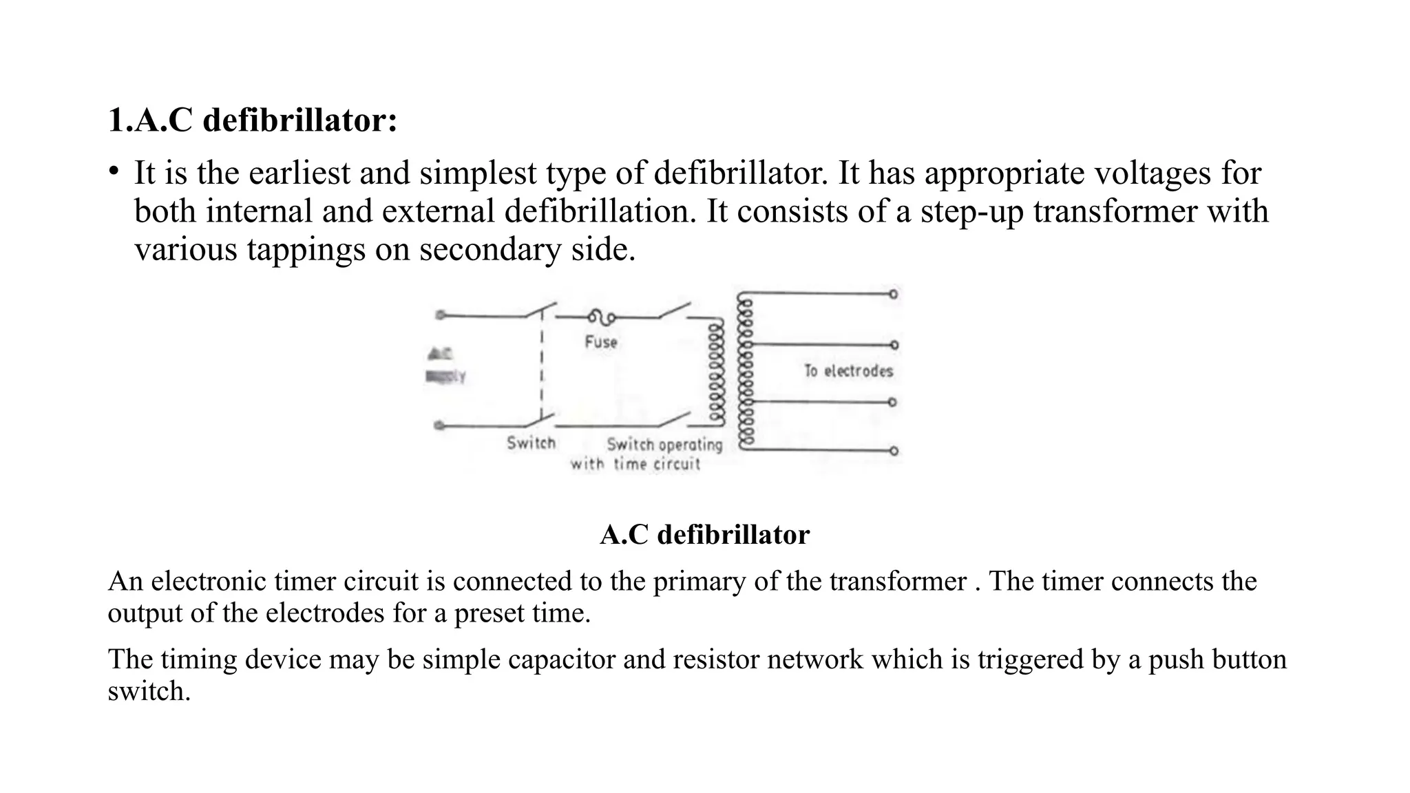
1.A.C defibrillator:
• Itis the earliest and simplest type of defibrillator. It has appropriate voltages for
both internal and external defibrillation. It consists of a step-up transformer with
various tappings on secondary side.
A.C defibrillator
An electronic timer circuit is connected to the primary of the transformer . The timer connects the
output of the electrodes for a preset time.
The timing device may be simple capacitor and resistor network which is triggered by a push button
switch.
113.
• The durationof shock may vary from 0.1-1sec depending upon the voltage to be applied.
• For safety the secondary coil of transformer should be isolated from earth so that there is any shock
risk to anyone.
• For external defibrillation the voltages are in the range from 250 to 750V. For internal defibrillation
the voltage is from 60 to 250 V.
• External defibrillation requires large currents for the simultaneous contraction of heart muscle fiber.
• This current also results in occasional burning of skin under the electrodes. Further it produces atrium
fibrillation while arresting ventricular fibrillation.
2. D.C defibrillator:
• D.C defibrillator would not produce undesirable side effects and at the same time it produces normal
heart beat effectively.
• Ventricular fibrillation is terminated by passing a high energy shock through discharging a capacitor
to exposed heart or chest of patient .
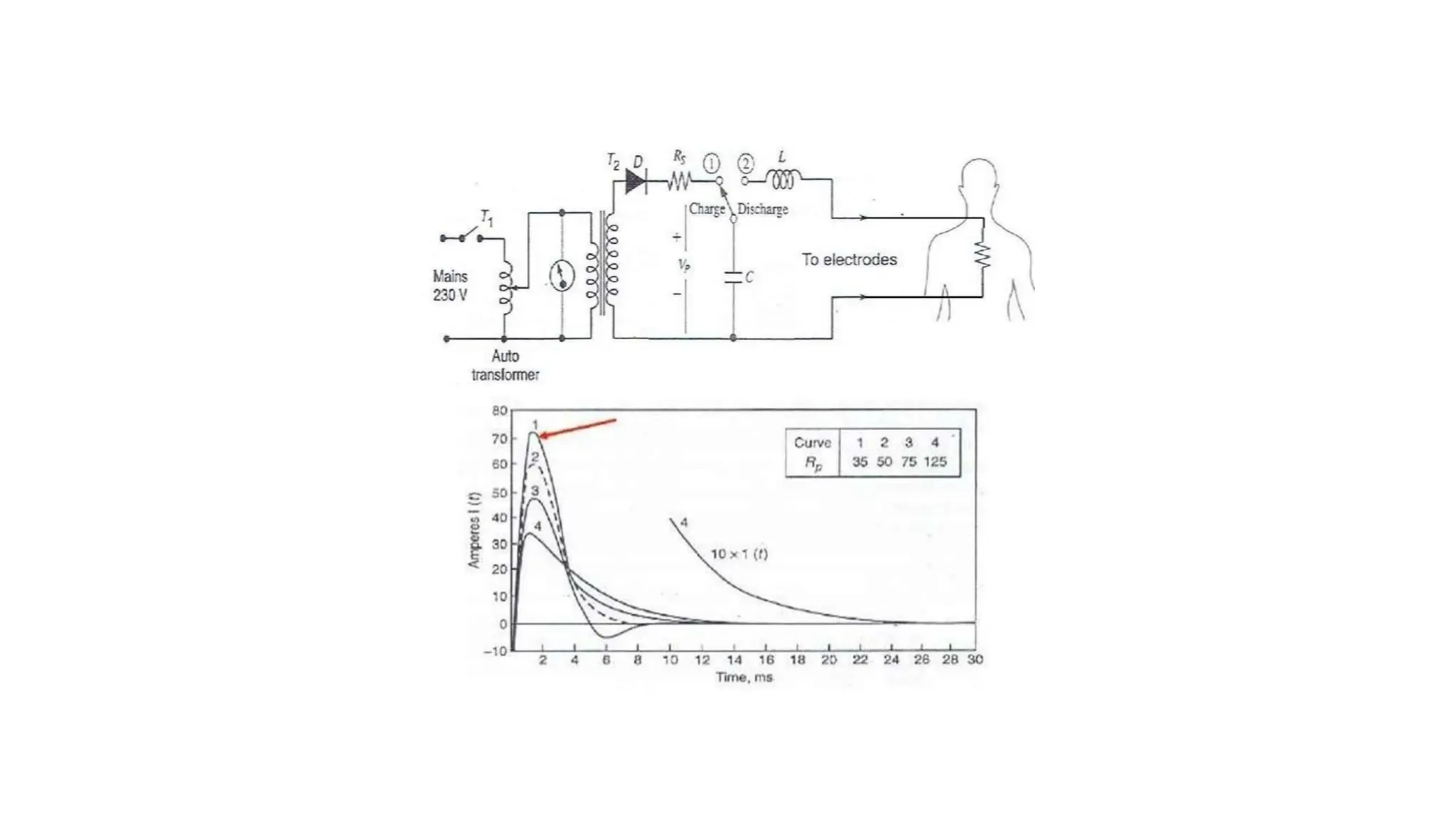
• A variable auto transformer T1 forms the primary of a high voltage transformer T2. The output
voltage of transformer T2 is rectified by a diode rectifier and is connected to a vacuum type high
voltage change over switch.
• In position ‗A‗ the switch is connected to one end of an oil filled capacitor.
114.
• In thisposition the capacitor charges to a voltage set by the positioning of auto
transformer.
• During the delivery of shock to patient a push button switch mounted on handle of
electrodes operated.
• The high voltage switch changes to position ‗B‗ and the capacitor is discharged
across the heart through electrodes.
• An inductor ‗L‗ is placed in one of the electrode leads so that the discharge from the
capacitor is slowed down by the induced counter voltage.
• The shape of waveform that appears across the electrodes will depend upon the value
of capacitor and inductor and its the amplitude depends upon the discharge resistance.
• The success of defibrillation depends upon the energy stored in the capacitor and not
with the voltage used. For internal defibrillation 100J of energy is required where as
for external defibrillation 400J are required. The discharging duration is from 5ms to
10ms.
116.
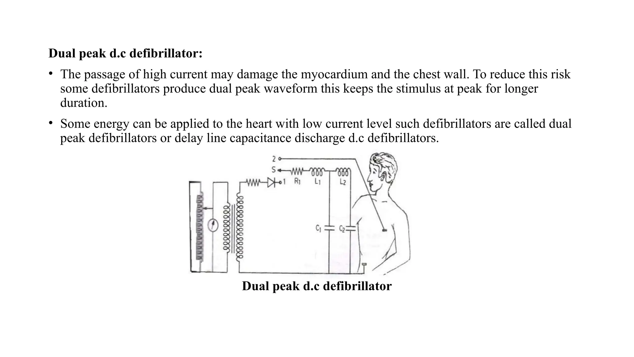
Dual peak d.cdefibrillator:
• The passage of high current may damage the myocardium and the chest wall. To reduce this risk
some defibrillators produce dual peak waveform this keeps the stimulus at peak for longer
duration.
• Some energy can be applied to the heart with low current level such defibrillators are called dual
peak defibrillators or delay line capacitance discharge d.c defibrillators.
Dual peak d.c defibrillator
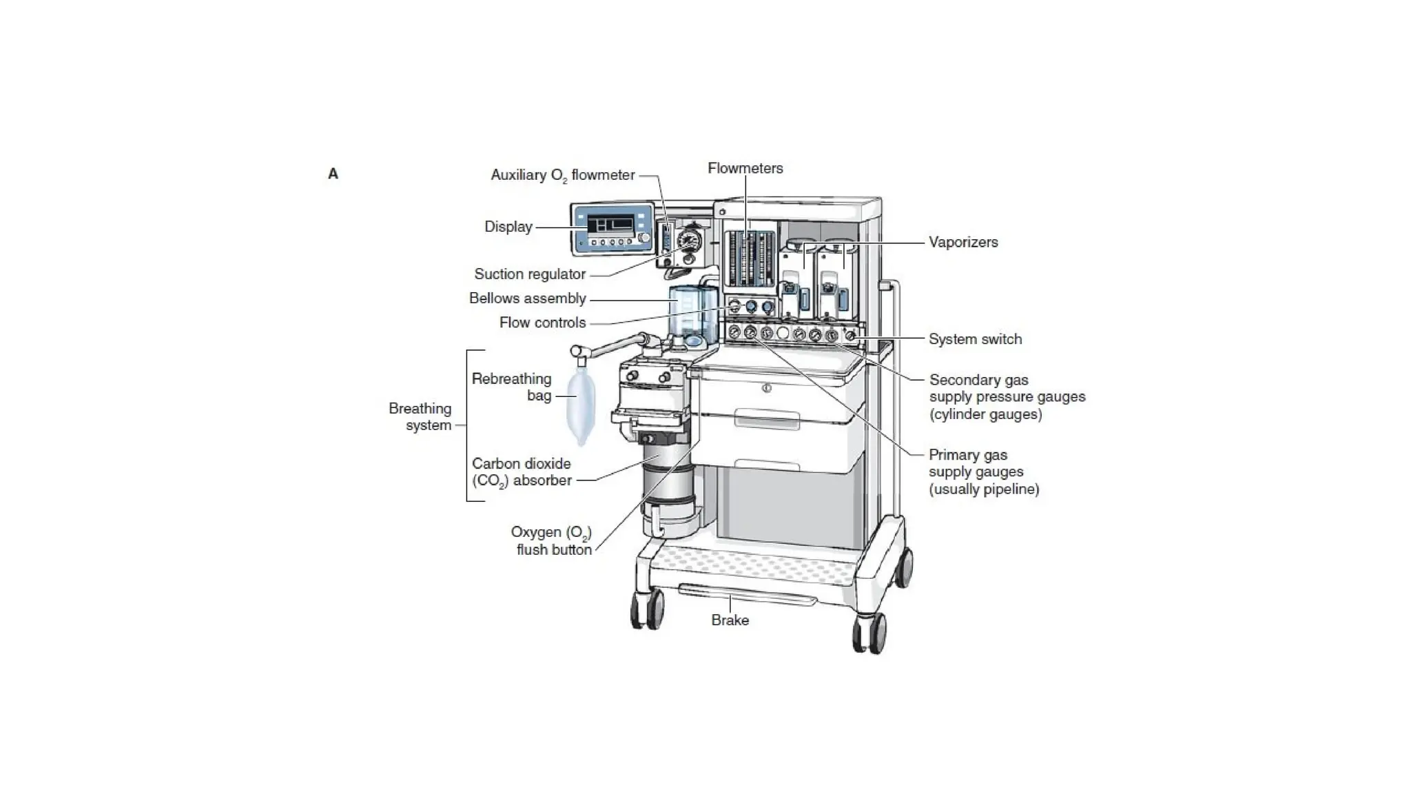
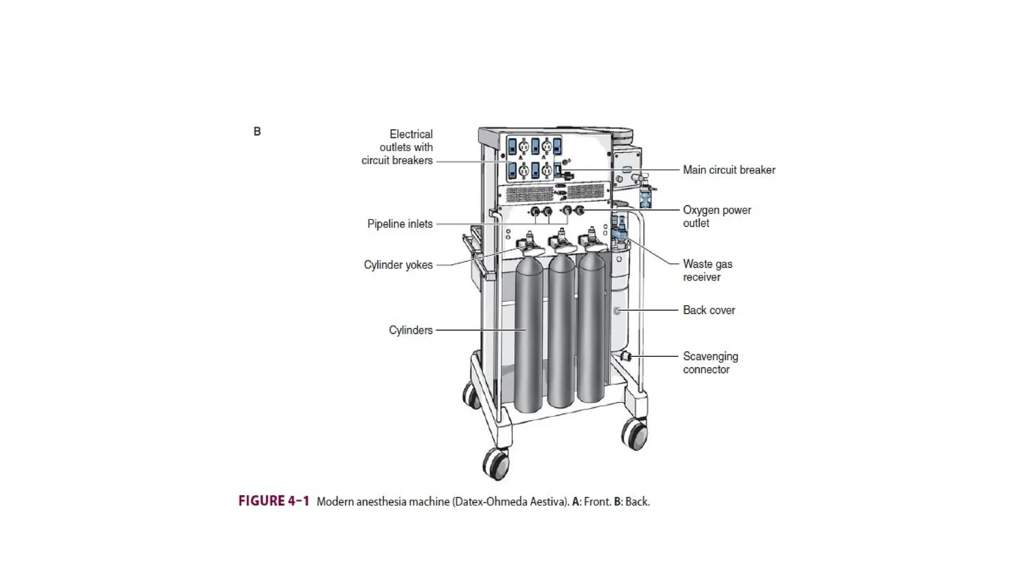
The Anesthesia Machine
•No piece of equipment is more intimately associated with the practice of anesthesiology than the
anesthesia machine .
• On the most basic level, the anesthesiologist uses the anesthesia machine to control the patient’s
ventilation and oxygen delivery and to administer inhalation anesthetics.
• Proper functioning of the machine is crucial for patient safety. Modern anesthesia machines have
become very sophisticated, incorporating many built-in safety features and devices, monitors, and
multiple micro-processors that can integrate and monitor all components.
• Additional monitors can be added externally and often still be fully integrated. Moreover, modu-
lar machine designs allow a wide variety of configurations and features within the same product
line.
• The term anesthesia workstation is therefore often used for modern anesthesia machines. There are
two major manufacturers of anesthesia machines in the United States, Datex-Ohmeda (GE
Healthcare) and Dräger Medical.
• Other manufacturers (eg, Mindray) produce anesthesia delivery systems. Anesthesia providers
should carefully review the operations manuals of the machines present in their clinical practice.
119.
• Much progresshas been made in reducing the number of adverse outcomes
arising from anesthetic gas delivery equipment, through redesign of equipment
and education.
• Misuse of anesthesia gas delivery systems is three times more likely than failure
of the device to cause equipment-related adverse outcomes.
• Equipment misuse is characterized as errors in preparation, maintenance, or
deployment of a device.
• Preventable anesthetic mis-haps are frequently traced to an operator’s lack of
familiarity with the equipment or a failure to check machine function, or both.
• These mishaps account for only about 2% of cases in the American Society of
Anesthesiologists’ (ASA) Closed Claims Project database.
• The breathing circuit was the most common single source of injury (39%); nearly
all damaging events were related to misconnects or disconnects. A misconnect
was defined as a